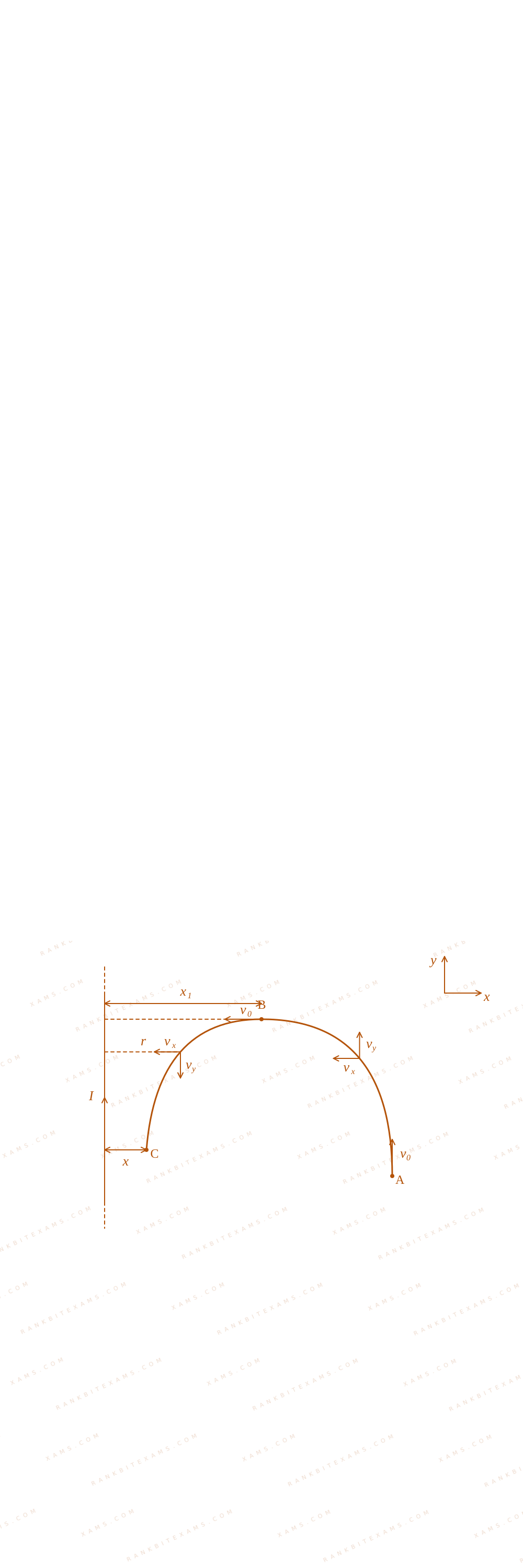
Consider a long thin conducting wire carrying a uniform current I. A particle having mass "M" and charge "q" is released at a distance "a" from the wire with a speed v₀$\mathbf{v}_0$ along the direction of current in the wire. The particle gets attracted to the wire due to magnetic force. The particle turns round when it is at distance x$\mathbf{x}$ from the wire. The value of x$\mathbf{x}$ is [μ₀$[\mu_0$ is vacuum permeability]
Analyzing motion from path phases A arrow B$\mathrm{A} \rightarrow \mathrm{B}$ and B arrow C$\mathrm{B} \rightarrow \mathrm{C}$ inside the coordinate field:
Coordinate trajectory analysis path diagram for Q6
B = μ₀ I2π r(- k)$$\vec{\mathrm{B}} = \frac{\mu_0 \mathrm{I}}{2\pi \mathrm{r}}(-\hat{\mathrm{k}})$$
The lorentz magnetic field acceleration rules dictate differential trajectory steps:
Solving this integration step gives the position node parameter:
x₁ = a e-(2π m v₀)/(μ₀ I q)$$x_1 = a e^{-\frac{2\pi m v_0}{\mu_0 I q}}$$
Compounding this loop interaction for the turning path phase B arrow C$\mathrm{B} \rightarrow \mathrm{C}$ gives:
Step 1: Final Solution Integration
x = x₁ e-(2π m v₀)/(μ₀ I q) = a e-(4π m v₀)/(μ₀ I q)$$x = x_1 e^{-\frac{2\pi m v_0}{\mu_0 I q}} = a e^{-\frac{4\pi m v_0}{\mu_0 I q}}$$
Matches criteria for option (4).
Pattern Recognition
Variable magnetic field cross-products result in dual exponential scaling metrics. Remember the total velocity magnitude stays fixed under zero work magnetic operations.
Keywords:#conducting wire carrying a uniform current#JEE Main 2025 Morning Q6#Moving Charges and Magnetism JEE Main 2025#Magnetic Force on a Charged Particle JEE Main 2025
More Moving Charges and Magnetism Previous-Year Questions — Page 6
Q54jee_main_2024_29_january_eveningMagnetic Force on a Charge
A charge of 4.0$4.0\ \mu\text{C}$ is moving with a velocity of 4.0 × 10⁶ ms⁻¹$4.0 \times 10^{6}\text{ ms}^{-1}$ along the positive y-axis under a magnetic field B$\vec{B}$ of strength (2 k) T$(2\hat{k})\text{ T}$. The force acting on the charge is x i N$x\hat{i}\text{ N}$. The value of x$x$ is ________.
Numerical Answer.Answer: 32 to 32
Solution
Related Formula
The magnetic force on a moving charge is given by the Lorentz force equation:
F = q ( v × B)$$\vec{F} = q (\vec{v} \times \vec{B})$$
Since j × k = i$\hat{j} \times \hat{k} = \hat{i}$:
F = 32 i N$$\vec{F} = 32\hat{i}\text{ N}$$
Comparing this to x i N$x\hat{i}\text{ N}$, we find:
x = 32$x = 32$
Pattern Recognition
Cross-product check: j × k = i$\hat{j} \times \hat{k} = \hat{i}$. The product of the scalar terms (4.0 × 10⁻⁶) × (4.0 × 10⁶) × 2$(4.0 \times 10^{-6}) \times (4.0 \times 10^6) \times 2$ immediately simplifies to 4 × 4 × 2 = 32$4 \times 4 \times 2 = 32$.
Chapter Mix
Class 12 Physics: Moving Charges and Magnetism
Qjee_main_2024_27_jan_morningMagnetic Field due to Long Straight Wire
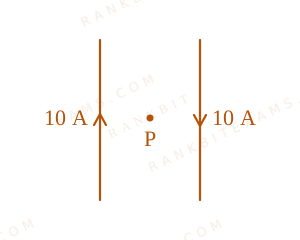
Two long, straight wires carry equal currents in opposite directions as shown in the figure. The separation between the wires is 5.0 cm$5.0\text{ cm}$. The magnitude of the magnetic field at a point P$P$ midway between the wires is ______ $\mu\text{T}$. (Given : μ₀ = 4π × 10⁻⁷ T ⁻¹$\mu_{0} = 4\pi \times 10^{-7}\text{ T}\cdot\text{m}\cdot\text{A}^{-1}$, and each wire carries a current of 10 A$10\text{ A}$).
The diagram maps two vertical wires carrying anti-parallel currents of 10 A separated by 5.0 cm, with central node P denoting the common field contribution site.
Numerical Answer.Answer: 160 to 160
Solution
Related Formula
B = (μ₀ i)/(2π r)$$B = \frac{\mu_0 i}{2\pi r}$$
Core Logic
Using the right-hand grip rule, both anti-parallel wire systems generate field arrays pointing in the exact same direction at the central midway coordinate. Hence, their field contributions add up directly:
Where i = 10 A$i = 10\text{ A}$, total distance = 5 cm r = 2.5 cm = 2.5 × 10⁻² m$= 5\text{ cm} \implies r = 2.5\text{ cm} = 2.5 \times 10^{-2}\text{ m}$.
Anti-parallel current pairs generate collaborative field additions inside their spatial boundary zone, rather than destructive structural cancellations.
Chapter Mix
Class 12 Physics: Moving Charges and Magnetism
Q34jee_main_2024_27_jan_morningLorentz Force
A proton moving with a constant velocity passes through a region of space without any change in its velocity.
If E$\vec{E}$ and B$\vec{B}$ represent the electric and magnetic fields respectively, then the region of space may have:
(A) E = 0, B = 0$E = 0, B = 0$
(B) E = 0, B ≠ 0$E = 0, B \neq 0$
(C) E ≠ 0, B = 0$E \neq 0, B = 0$
(D) E ≠ 0, B ≠ 0$E \neq 0, B \neq 0$
Choose the most appropriate answer from the options given below:
A.(A), (B) and (C) only$\text{(A), (B) and (C) only}$
B.(A), (C) and (D) only$\text{(A), (C) and (D) only}$
C.(A), (B) and (D) only$\text{(A), (B) and (D) only}$
D.(B), (C) and (D) only$\text{(B), (C) and (D) only}$
Solution
Related Formula
Fₙₑₜ = q E + q( v × B)$$\vec{F}_{\text{net}} = q\vec{E} + q(\vec{v} \times \vec{B})$$
Core Logic
For velocity to remain constant, the net force must be zero:
q E + q( v × B) = 0$$q\vec{E} + q(\vec{v} \times \vec{B}) = 0$$
Let's evaluate the cases:
Case (A): If E=0$E=0$ and B=0$B=0$, F = 0$\vec{F} = 0$. (Possible)
Case (B): If E=0$E=0$ and B ≠ 0$B \neq 0$, the magnetic force is zero if v$\vec{v}$ is parallel or antiparallel to B$\vec{B}$ (i.e., v × B = 0$\vec{v} \times \vec{B} = 0$). (Possible)
Case (C): If E ≠ 0$E \neq 0$ and B=0$B=0$, F = q E ≠ 0$\vec{F} = q\vec{E} \neq 0$, velocity must change. (Not possible)
Case (D): If E ≠ 0$E \neq 0$ and B ≠ 0$B \neq 0$, the electric and magnetic forces can balance each other perfectly if q E = -q( v × B)$q\vec{E} = -q(\vec{v} \times \vec{B})$. (Possible)
Step 1: Conclusion
Hence, statements (A), (B), and (D) represent valid situations where velocity can remain constant.
Pattern Recognition
Velocity filter / velocity selector setups utilize crossed fields where electric fields perfectly balance magnetic components, an archetype of Case (D).
Chapter Mix
Class 12 Physics: Moving Charges and Magnetism
Qjee_main_2024_29_jan_morningGalvanometer and its Conversions
A galvanometer having coil resistance 10 Ω$10 \, \Omega$ shows a full scale deflection for a current of 3 ~mA$3 \mathrm{~mA}$. For it to measure a current of 8 ~A$8 \mathrm{~A}$, the value of the shunt should be:
A.3 × 10⁻³ Ω$3 \times 10^{-3} \, \Omega$
B.4.85 × 10⁻³ Ω$4.85 \times 10^{-3} \, \Omega$
C.3.75 × 10⁻³ Ω$3.75 \times 10^{-3} \, \Omega$
D.2.75 × 10⁻³ Ω$2.75 \times 10^{-3} \, \Omega$
Solution
Related Formula
To convert a galvanometer into an ammeter, a small resistance called a shunt (S$S$) is connected in parallel with the galvanometer (G$G$):
Ig G = (I - Ig) S S = (Ig G)/(I - Ig)$$I_g G = (I - I_g) S \implies S = \frac{I_g G}{I - I_g}$$
where,
G$G$ = resistance of the galvanometer coil
Ig$I_g$ = full-scale deflection current of the galvanometer
I$I$ = total current to be measured
S$S$ = shunt resistance
Therefore, the required value of the shunt resistance is 3.75 × 10⁻³ Ω$3.75 \times 10^{-3} \, \Omega$.
Circuit diagram of conversion of a galvanometer into an ammeter using parallel shunt resistance for Q42
Pattern Recognition
Since I gg Ig$I \gg I_g$, the value I - Ig$I - I_g$ in the denominator can be approximated directly as I$I$ for a very accurate quick shortcut in choice selection: S ≈ (Ig G)/(I) = (0.03)/(8) = 3.75 × 10⁻³ Ω$S \approx \frac{I_g G}{I} = \frac{0.03}{8} = 3.75 \times 10^{-3} \, \Omega$.
Chapter Mix
Class 12 Physics: Moving Charges and Magnetism
Qjee_main_2024_29_jan_morningGalvanometer and its Conversions
The deflection in moving coil galvanometer falls from 25 divisions to 5 division when a shunt of 24 Ω$24 \, \Omega$ is applied. The resistance of galvanometer coil will be:
A.12 Ω$12 \, \Omega$
B.96 Ω$96 \, \Omega$
C.48 Ω$48 \, \Omega$
D.100 Ω$100 \, \Omega$
Solution
Related Formula
For a shunted galvanometer, the potential difference across the galvanometer is equal to the potential difference across the shunt resistor:
Ig G = (I - Ig) S$$I_g G = (I - I_g) S$$
Core Logic
Let the current sensitivity per division be x$x$.
Initially, without the shunt, the total current I$I$ gives a full scale deflection of 25 divisions:
I = 25x$I = 25x$
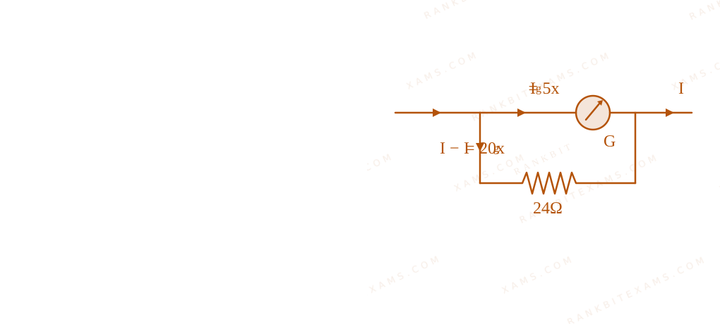
Schematic diagrams representing galvanometer before and after shunting for Q44
When the shunt (S = 24 Ω$S = 24 \, \Omega$) is connected in parallel, the current passing through the galvanometer branch (Ig$I_g$) corresponds to a deflection of 5 divisions:
Ig = 5x$I_g = 5x$
Schematic diagrams representing galvanometer before and after shunting for Q44
Therefore, the resistance of the galvanometer coil is 96 Ω$96 \, \Omega$.
Pattern Recognition
The deflection is directly proportional to the branch current. A drop from 25 divisions to 5 divisions means only (5)/(25) = (1)/(5)$\frac{5}{25} = \frac{1}{5}$ of the total current flows through the galvanometer, leaving (4)/(5)$\frac{4}{5}$ to go through the shunt. Hence, the galvanometer resistance must be 4 times the shunt resistance.
Chapter Mix
Class 12 Physics: Moving Charges and Magnetism
More Moving Charges and Magnetism Questions — jee_main_2025_28_jan_morning
Practice past-year questions one chapter at a time. Pick an exam → subject → chapter and get every PYQ for that topic — pulled together from all past papers — with the chapter's key formulas alongside.
