JEE Main · Physics ↓ Falling

Moving Charges and Magnetism appeared 37 times across 3 years — 4.3% of Physics. This question is from Magnetic Force on a Charged Particle.

Year 2026 2025 2024 Total
Questions 9 13 15 37

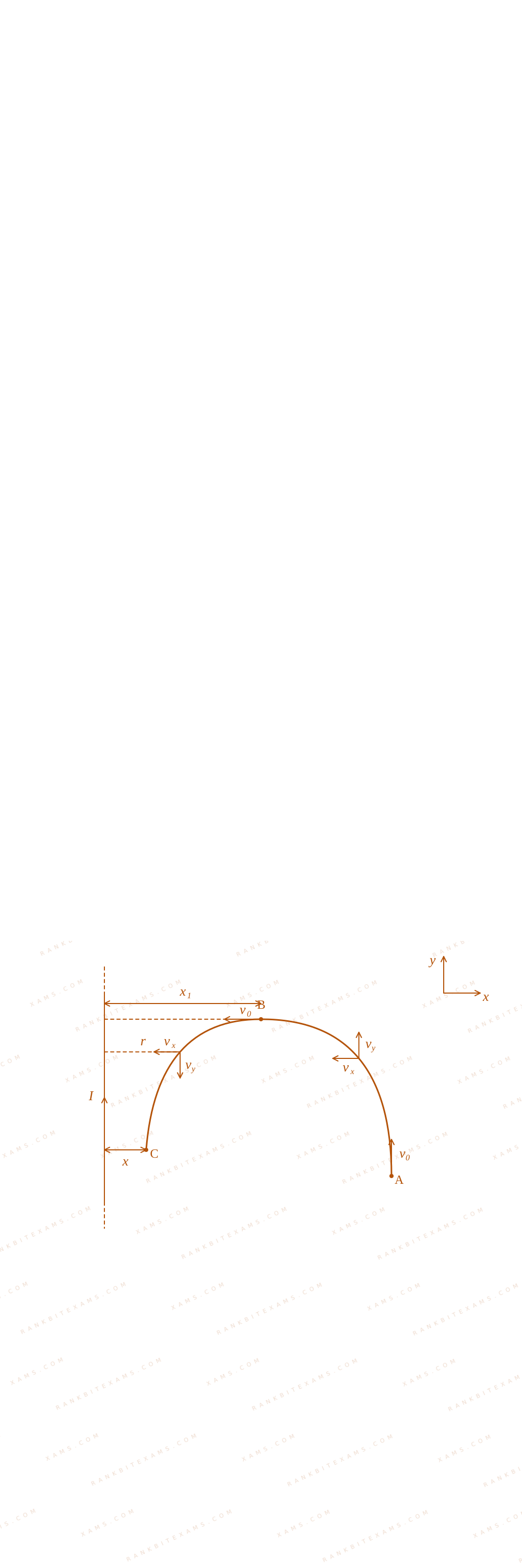
Consider a long thin conducting wire carrying a uniform current I. A particle having mass "M" and charge "q" is released at a distance "a" from the wire with a speed v₀ along the direction of current in the wire. The particle gets attracted to the wire due to magnetic force. The particle turns round when it is at distance x from the wire. The value of x is [μ₀ is vacuum permeability]

Solution & Explanation

Core Logic

Analyzing motion from path phases A arrow B and B arrow C inside the coordinate field:

Coordinate trajectory analysis path diagram for Q6

B = μ₀ I2π r(- k)

The lorentz magnetic field acceleration rules dictate differential trajectory steps:

∫v₀⁰ vₓ dvₓ√(v₀² - vₓ²) = - μ₀ I q2π m ∫ₐx₁ (dr)/(r)

Solving this integration step gives the position node parameter:

x₁ = a e-(2π m v₀)/(μ₀ I q)

Compounding this loop interaction for the turning path phase B arrow C gives:

Step 1: Final Solution Integration
x = x₁ e-(2π m v₀)/(μ₀ I q) = a e-(4π m v₀)/(μ₀ I q)

Matches criteria for option (4).

Pattern Recognition

Variable magnetic field cross-products result in dual exponential scaling metrics. Remember the total velocity magnitude stays fixed under zero work magnetic operations.

Chapter Mix

Class 12 Physics: Moving Charges and Magnetism

Reference Study Guides

More Moving Charges and Magnetism Previous-Year Questions — Page 7

Q56 jee_main_2024_30_january_evening Magnetic Field of a Square Loop
The current of 5 ~A flows in a square loop of sides 1 ~m is placed in air. The magnetic field at the centre of the loop is X√(2) × 10⁻⁷ T. The value of X is ________
Numerical Answer. Answer: 40 to 40

Solution

Related Formula
B = (μ₀ i)/(4π d) ( θ₁ + θ₂)
Core Logic

For a square loop of side length a, the perpendicular distance from the center to any side is d = (a)/(2). The angles subtended by the ends of one side at the center are θ₁ = θ₂ = 45^°. Since there are 4 identical sides contributing to the field in the same direction, the total magnetic field is 4 times the field due to one side.

Step 1: Calculate Field for One Side
B₁ = (μ₀ i)/(4π (a/2)) ( 45^° + 45^°) B₁ = 4π × 10⁻⁷ × 54π × 0.5 ( 1√(2) + 1√(2) ) B₁ = 10⁻⁷ × 50.5 × 2√(2) = 10 × 10⁻⁷ × √(2)
Step 2: Total Magnetic Field
Btotal = 4 × B₁ = 4 × 10√(2) × 10⁻⁷ ~T Btotal = 40√(2) × 10⁻⁷ ~T

Comparing with X√(2) × 10⁻⁷ T, we get X = 40.

Pattern Recognition

The magnetic field at the center of an n-sided regular polygon carrying current I and circumscribed by circle of radius R is B = (μ₀ n I)/(2π R) ((π)/(n)). Or simply use B = 4 × Bwire.

Chapter Mix

Class 12 Physics: Moving Charges and Magnetism
Q39 jee_main_2024_30_jan_morning Magnetic Field at the Center of a Loop
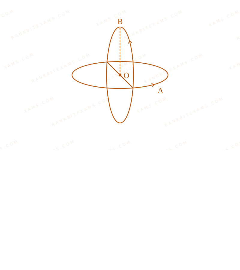
Two insulated circular loop A and B radius 'a' carrying a current of 'I' in the anti clockwise direction as shown in figure. The magnitude of the magnetic induction at the centre will be :
Magnetic Field at the Center of a Loop diagram for Q39 - JEE Main 2024 Morning
Two circular current carrying loops placed orthogonally.
  • A. √(2) μ₀ Ia
  • B. (μ₀ I)/(2 a)
  • C. μ₀ I√(2) a
  • D. (2 μ₀ I)/(a)

Solution

Related Formula
B = (μ₀ I)/(2R) Bₙₑₜ = √(B₁² + B₂²) (for mutually perpendicular fields)
Core Logic

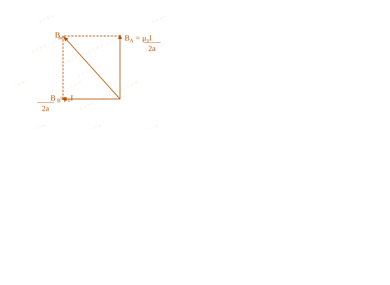
The two loops are mutually perpendicular to each other. The magnetic field at the center due to each loop acts along their respective normal axes, meaning the two resulting magnetic field vectors are orthogonal (90^° apart).

Vector resolution showing orthogonal B fields.
Two circular current carrying loops placed orthogonally.

Step 1: Calculate Individual Fields

Magnetic field at the center due to loop A:

BA = (μ₀ I)/(2a)

Magnetic field at the center due to loop B:

BB = (μ₀ I)/(2a)
Step 2: Resultant Magnetic Field

Since BA and BB are perpendicular to each other:

Bₙₑₜ = √(BA² + BB²) Bₙₑₜ = √(((μ₀ I)/(2a))² + ((μ₀ I)/(2a))²) Bₙₑₜ = (μ₀ I)/(2a) √(2) = √(2) μ₀ I2a = μ₀ I√(2) a
Pattern Recognition

When two identical physical sources generate orthogonal vector fields of magnitude B, the resultant is simply √(2)B.

Chapter Mix

Class 12 Physics: Moving Charges and Magnetism
Q51 jee_main_2024_30_jan_morning Magnetic Force on Current Carrying Wire
The horizontal component of earth's magnetic field at a place is 3.5 × 10⁻⁵ ~T. A very long straight conductor carrying current of √(2) ~A in the direction from South east to North West is placed. The force per unit length experienced by the conductor is × 10⁻⁶ ~N/m.
Numerical Answer. Answer: 35 to 35

Solution

Related Formula
F = I L B θ (F)/(L) = I B θ
Core Logic

Earth's horizontal magnetic field (BH) points strictly from South to North. The conductor is aligned from South-East to North-West. Thus, the angle θ between the current flow direction (SE to NW) and Earth's magnetic field (S to N) is exactly 45^°.

Step 1: Compute Force per Unit Length

BH = 3.5 × 10⁻⁵ ~T i = √(2) ~A θ = 45^°

(F)/( ) = i BH θ (F)/( ) = √(2) × (3.5 × 10⁻⁵) × 1√(2) (F)/( ) = 3.5 × 10⁻⁵ ~N/m (F)/( ) = 35 × 10⁻⁶ ~N/m
Step 2: Extract Value

The required multiplier for 10⁻⁶ is 35.

Pattern Recognition

Geographical alignments often yield clean angles like 45^° or 90^°. S-N field intersecting SE-NW current creates a 45^° angular intersection, perfectly canceling the √(2) amp current.

Chapter Mix

Class 12 Physics: Moving Charges and Magnetism Class 12 Physics: Magnetism and Matter
Q32 jee_main_2024_31_jan_evening Torque on a Current Loop
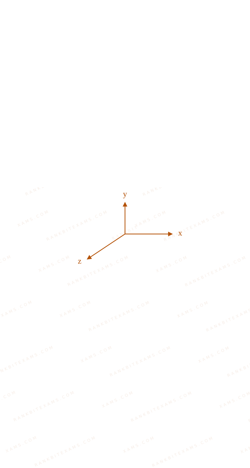
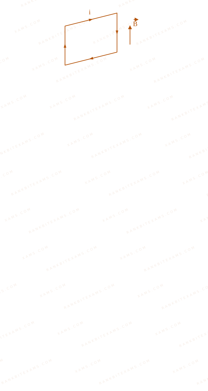
A uniform magnetic field of 2 × 10⁻³ T acts along positive Y-direction. A rectangular loop of sides 20 cm and 10 cm with current of 5 A is Y-Z plane. The current is in anticlockwise sense with reference to negative X axis. Magnitude and direction of the torque is :
  • A. 2 × 10⁻⁴ N-m along positive Z-direction
  • B. 2 × 10⁻⁴ N-m along negative Z-direction
  • C. 2 × 10⁻⁴ N-m along positive X-direction
  • D. 2 × 10⁻⁴ N-m along positive Y-direction

Solution

Related Formula
M = i A τ = M × B
Core Logic

The area vector A is perpendicular to the plane of the loop. According to the right-hand rule, an anticlockwise current observed from the negative X-axis means the area vector points in the negative X-direction.

Torque on a Current Loop diagram for Q32 - JEE Main 2024 Evening

Torque on a Current Loop diagram for Q32 - JEE Main 2024 Evening

Step 1: Calculating Magnetic Moment

Area of the loop, A = 0.2 m × 0.1 m = 0.02 m²

Magnetic moment vector:

M = i A M = 5 × (0.2) × (0.1) (- i) M = 0.1(- i) A m²
Step 2: Calculating Torque

The magnetic field is B = 2 × 10⁻³ j T.

Torque on the loop:

τ = M × B τ = 0.1(- i) × (2 × 10⁻³ j) τ = 2 × 10⁻⁴ (- k) N-m
Step 3: Final Direction

The - k direction corresponds to the negative Z-direction. Magnitude is 2 × 10⁻⁴ N-m.

Pattern Recognition

Identify the plane of the loop to get the possible normal vectors. Since the loop is in the Y-Z plane, A must be ± i. 'Anticlockwise from -X' fixes it as - i. Simply apply cross product - i × j = - k.

Chapter Mix

Class 12 Physics: Moving Charges and Magnetism
Q56 jee_main_2024_31_jan_evening Magnetic Field at the Center of a Coil
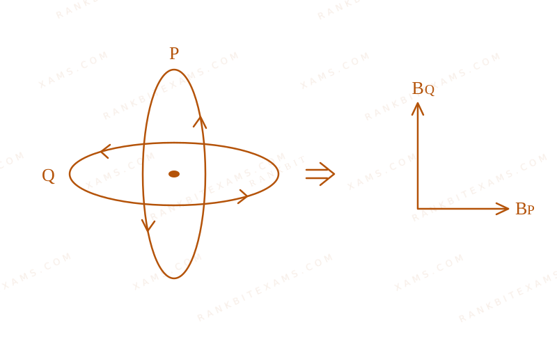
Two circular coils P and Q of 100 turns each have same radius of π cm. The currents in P and Q are 1 A and 2 A respectively. P and Q are placed with their planes mutually perpendicular with their centers coincide. The resultant magnetic field induction at the center of the coils is √(x) mT, where x = [Use μ₀ = 4π × 10⁻⁷ T m A⁻¹]
Numerical Answer. Answer: 20 to 20

Solution

Related Formula
B = (μ₀ N i)/(2r)

Bₙₑₜ = √(B₁² + B₂²) (for mutually perpendicular planes)

Core Logic

Calculate the magnetic field generated by each coil at their common center. Since the planes of the coils are perpendicular, their axial magnetic field vectors are also mutually perpendicular.

Magnetic Field at the Center of a Coil diagram for Q56 - JEE Main 2024 Evening

Step 1: Calculate Individual Fields

Radius r = π cm = π × 10⁻² m. N = 100 iP = 1 A, iQ = 2 A.

For coil P:

BP = (μ₀ N iP)/(2r) = (4π × 10⁻⁷) × 100 × 12 × π × 10⁻² BP = 4 × 10⁻⁵2 × 10⁻² = 2 × 10⁻³ T = 2 mT

For coil Q:

BQ = (μ₀ N iQ)/(2r) = (4π × 10⁻⁷) × 100 × 22 × π × 10⁻² = 4 × 10⁻³ T = 4 mT
Step 2: Calculate Resultant Field
Bₙₑₜ = √(BP² + BQ²) Bₙₑₜ = √(2² + 4²) = √(4 + 16) = √(20) mT
Step 3: Extract x

Given format is √(x) mT, so x = 20.

Pattern Recognition

For concentric perpendicular coils of same radius and turns, Bₙₑₜ = B₀ √(i₁² + i₂²) where B₀ is the base field for 1 A. This speeds up calculation considerably.

Chapter Mix

Class 12 Physics: Moving Charges and Magnetism
More Moving Charges and Magnetism Questions — jee_main_2025_28_jan_morning

Practice all Moving Charges and Magnetism previous-year questions →

Rankbit System
JEE Physics: Waves (+15.5%) | Electrostatics: Concentric Shells (-29.7%) | Modern Physics: Photoelectric Clones (+34.2%) | Mathematics: Definite Integrals (+18.1%) | Chemistry: Coordination Splitting (-11.4%) | JEE Physics: Waves (+15.5%) | Electrostatics: Concentric Shells (-29.7%) | Modern Physics: Photoelectric Clones (+34.2%) | Mathematics: Definite Integrals (+18.1%) | Chemistry: Coordination Splitting (-11.4%)
