JEE Main · Physics ↓ Falling

Moving Charges and Magnetism appeared 37 times across 3 years — 4.3% of Physics. This question is from Magnetic Force on a Charged Particle.

Year 2026 2025 2024 Total
Questions 9 13 15 37

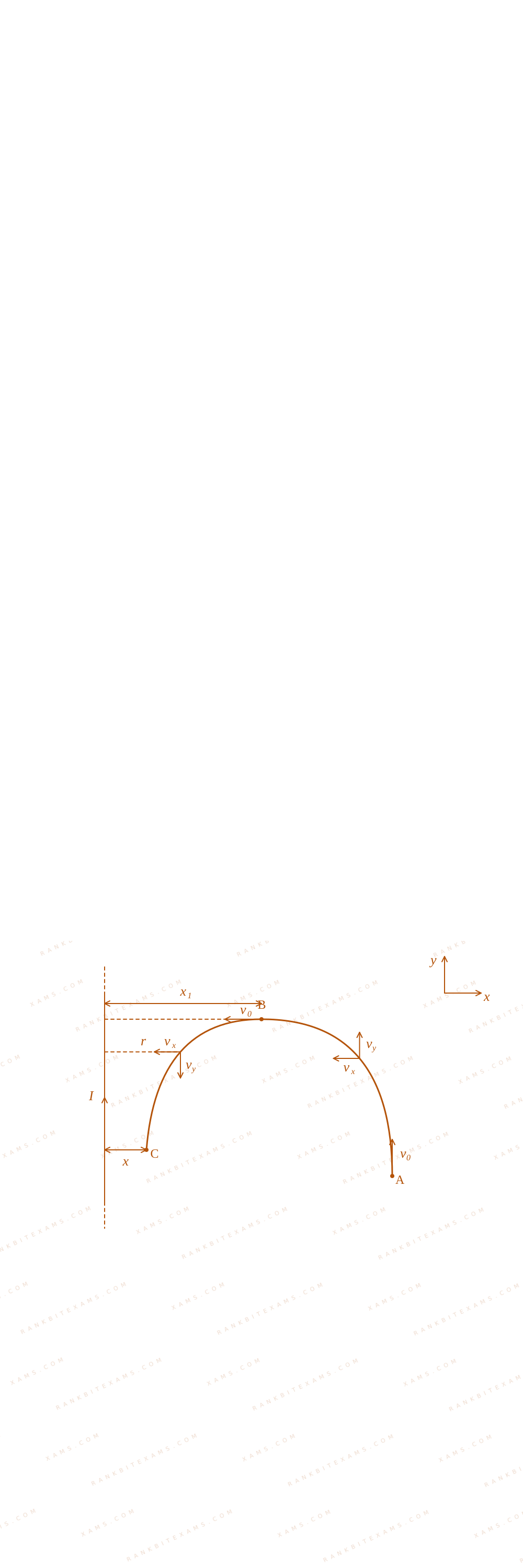
Consider a long thin conducting wire carrying a uniform current I. A particle having mass "M" and charge "q" is released at a distance "a" from the wire with a speed v₀ along the direction of current in the wire. The particle gets attracted to the wire due to magnetic force. The particle turns round when it is at distance x from the wire. The value of x is [μ₀ is vacuum permeability]

Solution & Explanation

Core Logic

Analyzing motion from path phases A arrow B and B arrow C inside the coordinate field:

Coordinate trajectory analysis path diagram for Q6

B = μ₀ I2π r(- k)

The lorentz magnetic field acceleration rules dictate differential trajectory steps:

∫v₀⁰ vₓ dvₓ√(v₀² - vₓ²) = - μ₀ I q2π m ∫ₐx₁ (dr)/(r)

Solving this integration step gives the position node parameter:

x₁ = a e-(2π m v₀)/(μ₀ I q)

Compounding this loop interaction for the turning path phase B arrow C gives:

Step 1: Final Solution Integration
x = x₁ e-(2π m v₀)/(μ₀ I q) = a e-(4π m v₀)/(μ₀ I q)

Matches criteria for option (4).

Pattern Recognition

Variable magnetic field cross-products result in dual exponential scaling metrics. Remember the total velocity magnitude stays fixed under zero work magnetic operations.

Chapter Mix

Class 12 Physics: Moving Charges and Magnetism
Reference Study Guides

More Moving Charges and Magnetism Previous-Year Questions — Page 2

Q38 jee_main_2026_24_january_evening Galvanometer to Ammeter Conversion
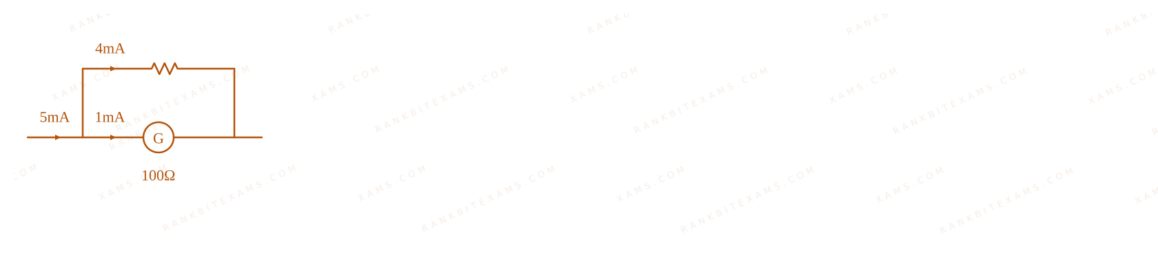
A moving coil galvanometer of resistance 100 Ω shows a full scale deflection for a current of 1 mA. The value of resistance required to convert this galvanometer into an ammeter, showing full scale deflection for a current of 5 mA, is ____ Ω
  • A. 25
  • B. 10
  • C. 0.5
  • D. 2.5

Solution

Related Formula
rₛ = (ig × G)/(i - ig) = (G)/(((i)/(ig) - 1))
Core Logic

Galvanometer to Ammeter Conversion diagram for Q38 - JEE Main 2026 Evening

Given: Galvanometer resistance, G = 100 Ω Full scale deflection current, ig = 1 mA Target current, i = 5 mA

Step 1: Calculate Shunt Resistance

Using the shunt resistance formula:

rₛ = (100)/(((5)/(1) - 1)) rₛ = (100)/(4) = 25 Ω
Pattern Recognition

When upgrading range n times (n = i / ig), the required parallel shunt is simply G / (n - 1).

Chapter Mix

Class 12 Physics: Moving Charges and Magnetism
Q34 jee_main_2026_28_january_morning Magnetic Force between Two Parallel Currents
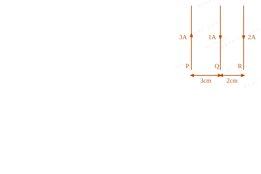
Three long straight wires carrying current are arranged mutually parallel as shown in the figure. The force experienced by 15 cm length of wire Q is ____.
Three parallel current carrying wires diagram for Q34
Three vertical wires P, Q, R carrying 3A (up), 1A (down), and 2A (down) separated by 3cm and 2cm respectively.
(μ₀ = 4π × 10⁻⁷T· m / A)
  • A. 6 × 10⁻⁷ ~N towards P
  • B. 6 × 10⁻⁶ ~N towards R
  • C. 6 × 10⁻⁷ ~N towards R
  • D. 6 × 10⁻⁶ ~N towards P

Solution

Related Formula
F = (μ₀ I₁ I₂ )/(2π d)
Core Logic

Wires with current in opposite directions repel each other. Wires with current in the same direction attract each other. Calculate the individual force vectors on wire Q due to wires P and R.

Step 1: Force due to Wire P

Wire P (3A up) and Wire Q (1A down) carry current in opposite directions. So, P repels Q towards the right (towards R).

FPQ = (μ₀ IP IQ )/(2π d₁) = μ₀ (3)(1) 2π (3 × 10⁻²)
Step 2: Force due to Wire R

Wire R (2A down) and Wire Q (1A down) carry current in the same direction. So, R attracts Q towards the right (towards R).

FRQ = (μ₀ IR IQ )/(2π d₂) = μ₀ (2)(1) 2π (2 × 10⁻²)
Step 3: Net Force Calculation

Both forces act in the same direction (towards R).

Fₙₑₜ = FPQ + FRQ = (μ₀)/(2π) IQ ( (IP)/(d₁) + (IR)/(d₂) ) Fₙₑₜ = 2 × 10⁻⁷ × 1 × ( 33 × 10⁻² + 22 × 10⁻² ) × 15 × 10⁻² = 2 × 10⁻⁷ × ( 110⁻² + 110⁻² ) × 15 × 10⁻² = 2 × 10⁻⁷ × (200) × 0.15 = 400 × 10⁻⁷ × 0.15 = 60 × 10⁻⁷ = 6 × 10⁻⁶ ~N
Step 4: Direction

The net force is 6 × 10⁻⁶ ~N towards R.

Pattern Recognition

Always map the direction (attract/repel) before plugging in numbers. Same direction = Attract. Opposite direction = Repel.

Chapter Mix

Class 12 Physics: Moving Charges and Magnetism
Q43 jee_main_2026_28_january_morning Magnetic Field on the Axis of a Circular Loop
The magnetic field at the centre of a current carrying circular loop of radius R is 16 . The magnetic field at a distance x = √(3) R on its axis from the centre is ____ .
  • A. 2√(2)
  • B. 4
  • C. 2
  • D. 8

Solution

Related Formula
Bcentre = (μ₀ I)/(2R) Bₐₓᵢₛ = μ₀ I R²2(x² + R²)3/2
Core Logic

Substitute the expression for Bcentre into the equation for Bₐₓᵢₛ by evaluating the denominator with x = √(3)R.

Step 1: Using Center Field
Bcentre = (μ₀ I)/(2R) = 16
Step 2: Calculating Axial Field

Substitute x = √(3)R into the axial field formula:

Bₐₓᵢₛ = μ₀ I R²2( (√(3)R)² + R² )3/2 = μ₀ I R²2(3R² + R²)3/2 = μ₀ I R²2(4R²)3/2
Step 3: Final Deduction
= (μ₀ I R²)/(2(8R³)) = (μ₀ I)/(16R) = (1)/(8) ( (μ₀ I)/(2R) ) = (1)/(8) × 16 = 2
Pattern Recognition

A classic standard derivation: at x = √(3)R, the field is 1/8 of the center field. At x = R, it's 1/(2√(2)). Committing these to memory saves 60 seconds.

Chapter Mix

Class 12 Physics: Moving Charges and Magnetism
Q39 jee_main_2026_28_january_evening Magnetic Field of a Cylindrical Conductor
A long cylindrical conductor with large cross section carries an electric current distributed uniformly over its cross-section. Magnetic field due to this current is: A. maximum at either ends of the conductor and minimum at the midpoint B. maximum at the axis of the conductor C. minimum at the surface of the conductor D. minimum at the axis of the conductor E. same at all points in the cross-section of the conductor Choose the correct answer from the options given below:
  • A. D Only
  • B. A, D Only
  • C. B, C Only
  • D. E Only

Solution

Related Formula

For a solid cylinder carrying uniform current density: Inside (r < R):

B = (μ₀ I r)/(2π R²)

Outside (r ≥ R):

B = (μ₀ I)/(2π r)
Core Logic

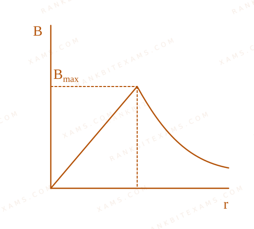
Solution for Magnetic Field of a Cylindrical Conductor
From the formula for the magnetic field inside the solid cylinder, B is directly proportional to the radial distance r from the axis. Thus, at the axis (r = 0), B = 0 (which is its absolute minimum). At the surface (r = R), B reaches its maximum value B = (μ₀ I)/(2π R).

Step 1: Evaluating the Statements

Statement A: Incorrect (B depends on radial distance, not longitudinal position). Statement B: Incorrect (B is minimum at the axis). Statement C: Incorrect (B is maximum at the surface). Statement D: Correct (B is zero at the axis). Statement E: Incorrect (B varies with r).

Pattern Recognition

Graph of B vs r for a uniform solid cylinder is a straight line passing through origin up to r=R, then a hyperbola 1/r outside. Zero at axis, max at surface.

Chapter Mix

Class 12 Physics: Moving Charges and Magnetism

Q2 jee_main_2025_02_april_evening Moving Coil Galvanometer
In a moving coil galvanometer, two moving coils M₁ and M₂ have the following particulars: aligned R₁ &= 5 Ω, N₁ = 15, A₁ = 3.6 × 10⁻³ m², B₁ = 0.25 T R₂ &= 7 Ω, N₂ = 21, A₂ = 1.8 × 10⁻³ m², B₂ = 0.50 T aligned Assuming that torsional constant of the springs are same for both coils, what will be the ratio of voltage sensitivity of M₁ and M₂ ?
  • A. 1:1
  • B. 1:4
  • C. 1:3
  • D. 1:2

Solution

Related Formula
Voltage Sensitivity (Vₛ) = (θ)/(V) = (N B A)/(C R)

where: N = number of turns B = magnetic field A = area of the coil C = torsional constant of the spring R = resistance of the coil

Core Logic

Since the torsional constant C is the same for both coils, the ratio of voltage sensitivities of M₁ and M₂ is:

((Vₛ)₁)/((Vₛ)₂) = ((N₁ A₁ B₁)/(N₂ A₂ B₂)) · ((R₂)/(R₁))

We are given the following values:

  • Coil 1: R₁ = 5 Ω, N₁ = 15, A₁ = 3.6 × 10⁻³ m², B₁ = 0.25 T
  • Coil 2: R₂ = 7 Ω, N₂ = 21, A₂ = 1.8 × 10⁻³ m², B₂ = 0.50 T
Step 1: Calculate the ratio

Substitute the values into the formula:

((Vₛ)₁)/((Vₛ)₂) = ( 15 × 3.6 × 10⁻³ × 0.2521 × 1.8 × 10⁻³ × 0.50) × (7)/(5)

Simplify the terms within the brackets:

  • 3.6 × 10⁻³1.8 × 10⁻³ = 2
  • (0.25)/(0.50) = (1)/(2)
(15 × 2 × (1)/(2))/(21) = (15)/(21) = (5)/(7)

Multiplying by (R₂)/(R₁) = (7)/(5):

((Vₛ)₁)/((Vₛ)₂) = (5)/(7) × (7)/(5) = 1

Thus, the ratio is 1:1.

Pattern Recognition

Sees: Galvanometer sensitivity comparison with different parameters. Trap: Confusing Current Sensitivity with Voltage Sensitivity. Current sensitivity is (NBA)/(C) (independent of R), while voltage sensitivity is (NBA)/(C R) (depends on R). Shortcut: Write the ratio as ((Iₛ)₁)/((Iₛ)₂) × (R₂)/(R₁) to keep calculations clean.

Chapter Mix

Class 12 Physics: Moving Charges and Magnetism

More Moving Charges and Magnetism Questions — jee_main_2025_28_jan_morning

Practice all Moving Charges and Magnetism previous-year questions →

Rankbit System
JEE Physics: Waves (+15.5%) | Electrostatics: Concentric Shells (-29.7%) | Modern Physics: Photoelectric Clones (+34.2%) | Mathematics: Definite Integrals (+18.1%) | Chemistry: Coordination Splitting (-11.4%) | JEE Physics: Waves (+15.5%) | Electrostatics: Concentric Shells (-29.7%) | Modern Physics: Photoelectric Clones (+34.2%) | Mathematics: Definite Integrals (+18.1%) | Chemistry: Coordination Splitting (-11.4%)