JEE Main · Physics → Steady

Current Electricity appeared 50 times across 3 years — 5.8% of Physics. This question is from Combination of Resistors.

Year 2026 2025 2024 Total
Questions 18 13 19 50

A wire of resistance R is bent into an equilateral triangle and an identical wire is bent into a square. The ratio of resistance between the two end points of an edge of the triangle to that of the square is

Solution & Explanation

Related Formula
R = ρ A R ∝
Core Logic

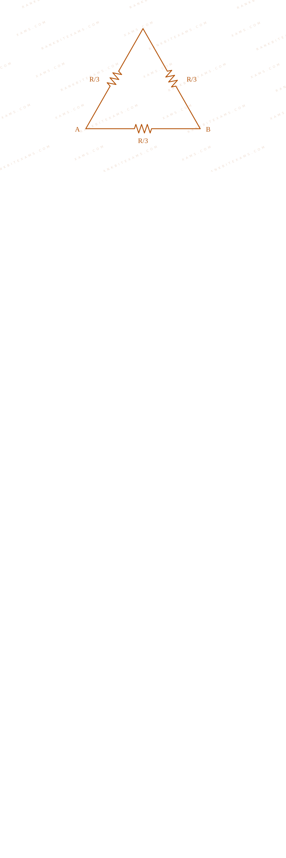
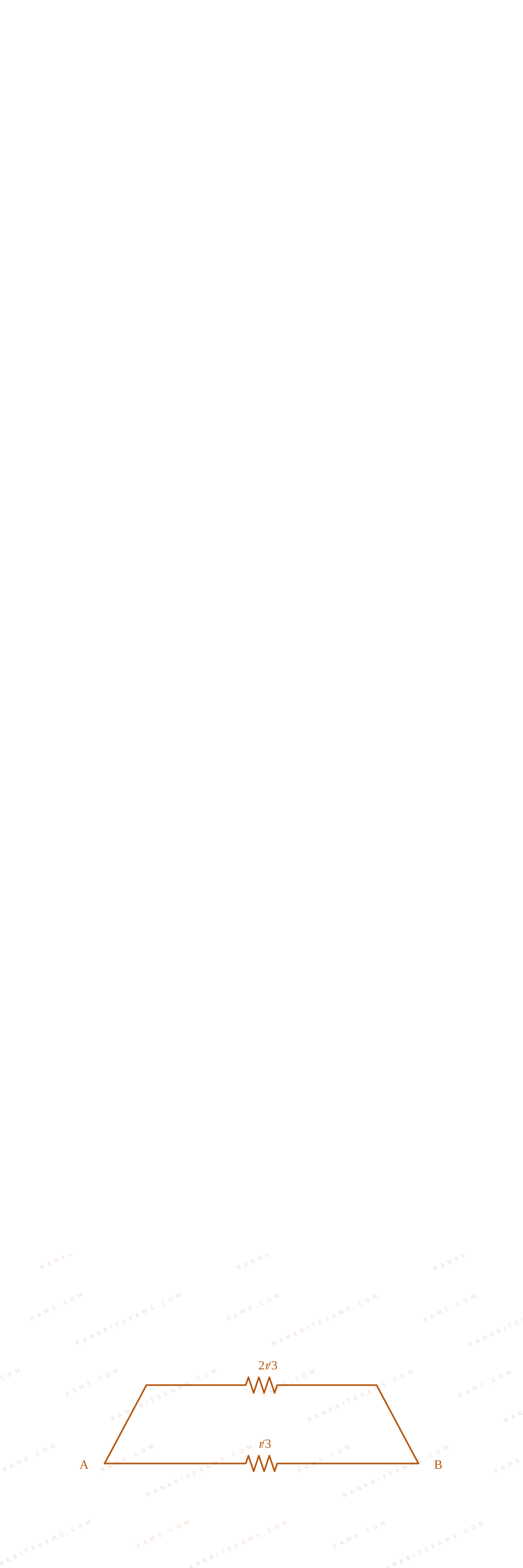
For the equilateral triangle, the total resistance R is divided into three equal line parts of value R3 each:

Visual representation of triangle and square edge divisions for Q15

Visual representation of triangle and square edge divisions for Q15

An edge configuration places one part in parallel with the other two series steps:

(Req)₁ = ( 2R3) · ( R3) 2R3 + R3 = (2)/(9)R

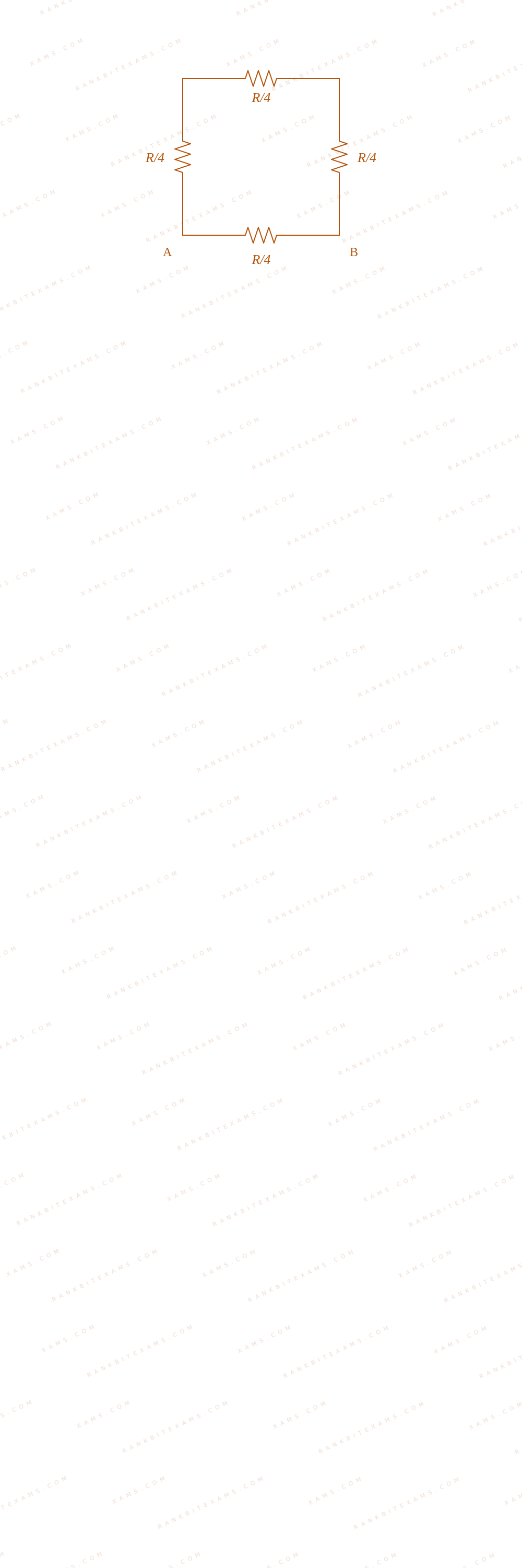
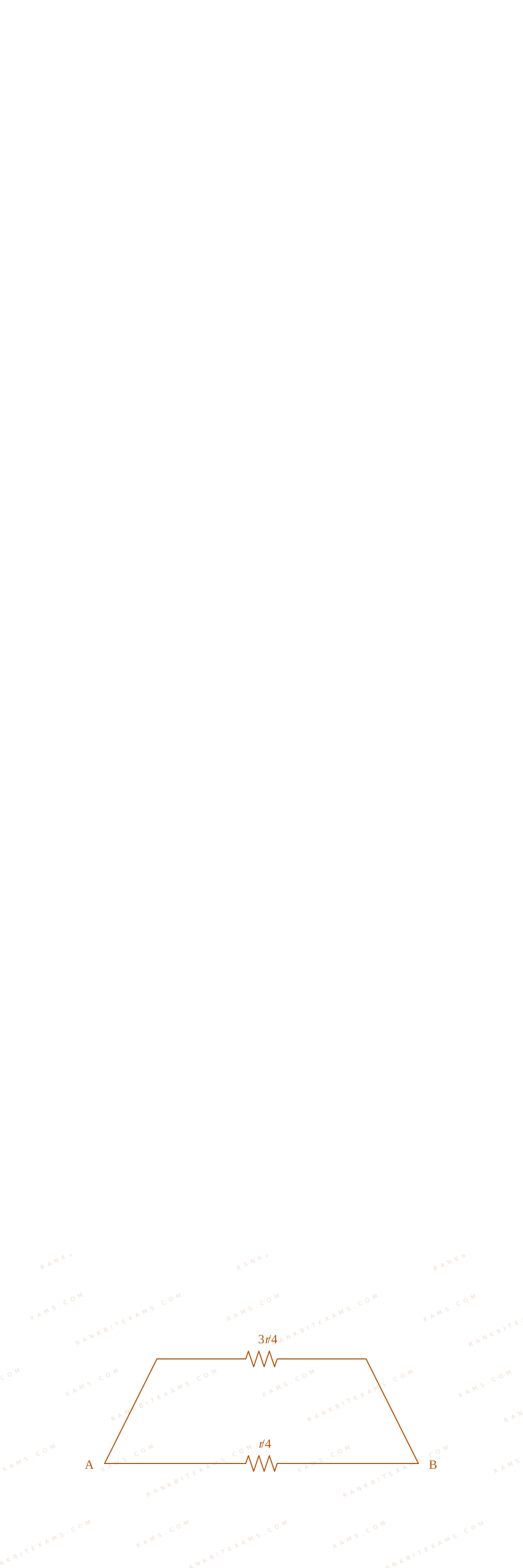
For the square, the wire resistance R divides into four parts of R4 each:

Visual representation of triangle and square edge divisions for Q15

Visual representation of triangle and square edge divisions for Q15

An edge calculation pairs one section in parallel with the remaining three loops in series:

(Req)₂ = ( 3R4) · ( R4) 3R4 + R4 = (3)/(16)R

Taking the ratio between these geometric layouts:

Step 1: Final Ratio Calculation
(Req)₁(Req)₂ = (2)/(9)R(3)/(16)R = (32)/(27)

This selects option (4).

Pattern Recognition

For a regular polygon with N identical sides formed from a wire of resistance R, the resistance across one edge is always given by (N-1)N²R.

Chapter Mix

Class 12 Physics: Current Electricity

Reference Study Guides

More Current Electricity Previous-Year Questions — Page 6

Q25 jee_main_2025_03_april_morning Galvanometer/Ammeter with Shunt Resistance
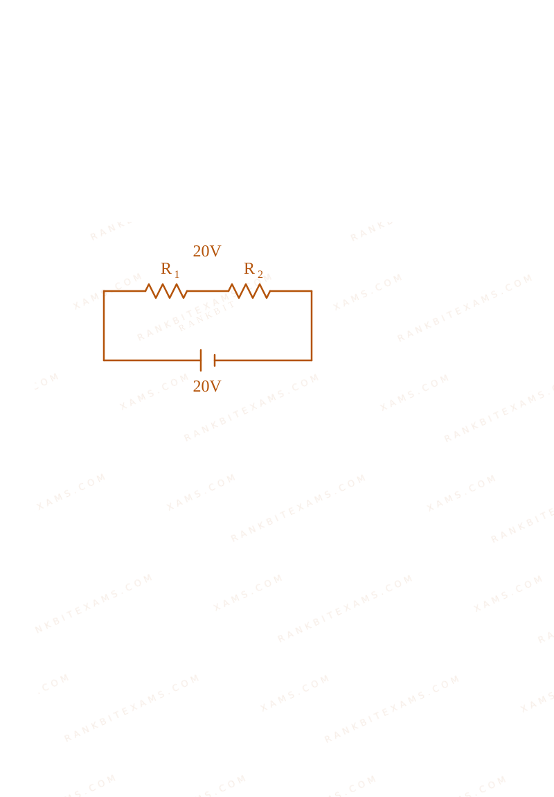
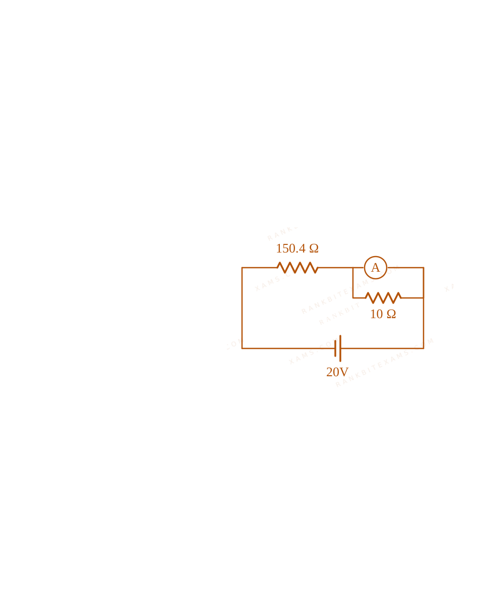
In the figure shown below, a resistance of 150.4Ω is connected in series to an ammeter A of resistance 240Ω. A shunt resistance of 10Ω is connected in parallel with the ammeter. The reading of the ammeter is ________ mA.
Series parallel circuit showing ammeter with shunt for Q25
A circuit schematic containing a 20V battery connected in series with a 150.4 ohm resistor and a parallel combination of a 240 ohm ammeter and a 10 ohm shunt resistor.
Numerical Answer. Answer: 5 to 5

Solution

Related Formula

Parallel combination of ammeter (RG = 240Ω) and shunt (S = 10Ω):

Rparallel = (RG · S)/(RG + S)

Total equivalent resistance:

Req = Rₛₑᵣᵢₑₛ + Rparallel

Current Divider Rule:

Iammeter = Itotal · ((S)/(RG + S))
Core Logic

Let's first calculate the equivalent resistance of the parallel branch (ammeter + shunt):

Rparallel = (240 × 10)/(240 + 10) = (2400)/(250) = 9.6Ω

Now, add the series resistance (150.4Ω) to find the total equivalent resistance of the circuit:

Req = 150.4 + 9.6 = 160Ω
Step 1: Finding Total Current

Use Ohm's Law to calculate the total current Itotal drawn from the 20~V battery:

Itotal = VReq = (20)/(160) = 0.125~A
Step 2: Calculating Ammeter Current

Using the Current Divider Rule, calculate the current Iammeter flowing through the 240Ω ammeter branch:

Iammeter = Itotal × (10)/(240 + 10) = 0.125 × (10)/(250) Iammeter = 0.125 × (1)/(25) = 0.005~A

Convert this into milliamperes (mA):

Iammeter = 0.005 × 1000 = 5~mA

Therefore, the reading of the ammeter is 5~mA.
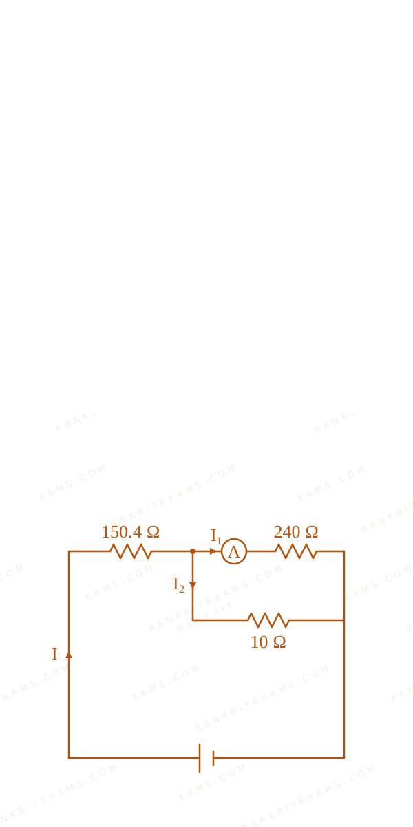
Simplified equivalent circuit showing ammeter shunt current split for Q25
A circuit schematic containing a 20V battery connected in series with a 150.4 ohm resistor and a parallel combination of a 240 ohm ammeter and a 10 ohm shunt resistor.
Simplified equivalent circuit showing ammeter shunt current split for Q25
A circuit schematic containing a 20V battery connected in series with a 150.4 ohm resistor and a parallel combination of a 240 ohm ammeter and a 10 ohm shunt resistor.

Pattern Recognition

Notice how nicely the numbers are set up in JEE Mains questions! The parallel combination of 240Ω and 10Ω yields exactly 9.6Ω, which beautifully combines with 150.4Ω to form a perfect integer sum of 160Ω. This tells you that your intermediate steps are absolutely correct!

Chapter Mix

Class 12 Physics: Current Electricity: Measuring Devices
Q2 jee_main_2025_04_april_evening Electric Power
There are 'n' number of identical electric bulbs, each is designed to draw a power p independently from the mains supply. They are now joined in series across the main supply. The total power drawn by the combination is:
  • A. np
  • B. pn²
  • C. (p)/(n)
  • D. p

Solution

Related Formula
P = (V²)/(R)

For series combination:

Rₛ = R₁ + R₂ + + Rₙ
Core Logic

Since the bulbs are identical, each has a resistance R = (V²)/(p). When n identical bulbs are connected in series, the total equivalent resistance becomes: Rₛ = nR

Step 1: Calculate Combined Power

The total power drawn across the same mains supply V is:

Pₛ = (V²)/(Rₛ) = (V²)/(nR) = (1)/(n) ((V²)/(R)) = (p)/(n)
Pattern Recognition

Identical appliances connected in series scale down their combined power inversely with count (Pₙₑₜ = P/n), identical appliances in parallel scale up combined power linearly (Pₙₑₜ = nP).

Chapter Mix

Class 12 Physics: Current Electricity

Q6 jee_main_2025_04_april_evening Combination of Resistors
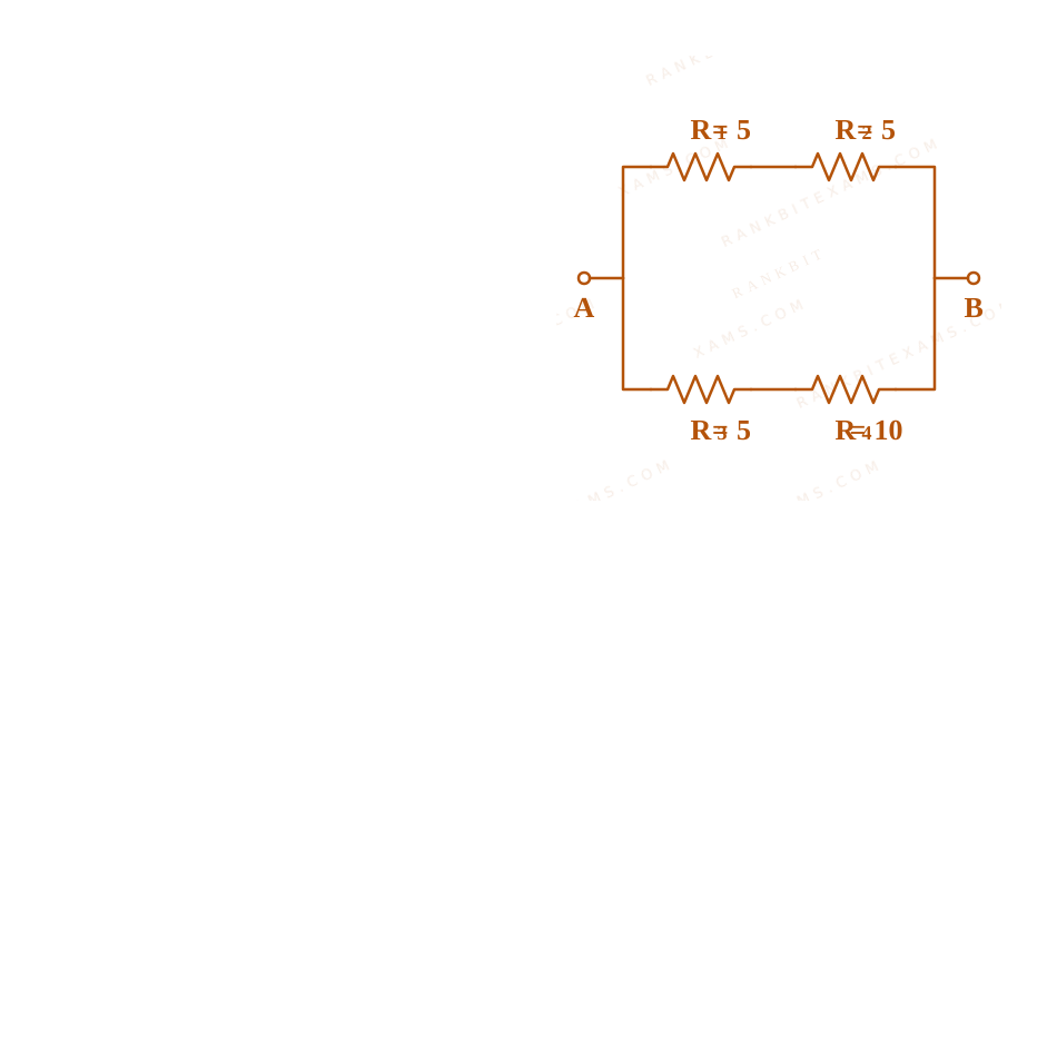
From the combination of resistors with resistance values R₁=R₂=R₃=5 Ω and R₄=10 Ω, which of the following combination is the best circuit to get an equivalent resistance of 6 Ω?
  • A.
  • B.
  • C.
  • D.

Solution

Related Formula

Series combination: Rₛ = Rₐ + Rb Parallel combination:

(1)/(Rₚ) = (1)/(R₁) + (1)/(R₂) Rₚ = (R₁ R₂)/(R₁ + R₂)
Core Logic

Let's check option (1): Top branch has R₁ and R₂ in series: Rₜₒₚ = 5 + 5 = 10 Ω. Bottom branch has R₃ and R₄ in series: Rbottom = 5 + 10 = 15 Ω.

Step 1: Calculate Equivalent Parallel Resistance

These two branches are connected in parallel, so the total equivalent resistance is:

Rₚ = (10 × 15)/(10 + 15) = (150)/(25) = 6 Ω

This matches the target value of 6 Ω perfectly.

Circuit diagram analysis for 6 ohm equivalent resistance

Pattern Recognition

Look for symmetric partitions. Standard combinations of values like 10 Ω and 15 Ω yield exactly 6 Ω in parallel.

Chapter Mix

Class 12 Physics: Current Electricity

Q jee_main_2025_04_april_morning Electric Current and Charge Flow
Current passing through a wire as function of time is given as I(t)=0.02t+0.01~A. The charge that will flow through the wire from t=1~s to t=2~s is:
  • A. 0.06 C
  • B. 0.02 C
  • C. 0.07 C
  • D. 0.04 C

Solution

Related Formula
q = ∫t₁t₂ I(t) dt
Core Logic

Given: I(t) = (0.02t + 0.01) A Limits: t₁ = 1 s, t₂ = 2 s

Step 1: Perform Definite Integration
q = ∫₁² (0.02t + 0.01) dt q = [ 0.02(t²)/(2) + 0.01t ]₁² = [ 0.01t² + 0.01t ]₁² q = [ 0.01(2)² + 0.01(2) ] - [ 0.01(1)² + 0.01(1) ] q = [0.04 + 0.02] - [0.01 + 0.01] = 0.06 - 0.02 = 0.04 C

Hence, the total charge flowing through the wire is 0.04 C.

Pattern Recognition

Definite integration of a linear current function can also be verified geometrically by calculating the area of the trapezoid under the I--t curve:

Area = (I(1) + I(2))/(2) × (2 - 1) = (0.03 + 0.05)/(2) × 1 = 0.04 C
Evaluation Rubric / Model Answer

Option D: 0.04 C

Chapter Mix

Class 12 Physics: Current Electricity

Q23 jee_main_2025_24_jan_morning Combination of Resistors
A wire of resistance 9Ω is bent to form an equilateral triangle. Then the equivalent resistance across any two vertices will be ______ ohm.
Numerical Answer. Answer: 2 to 2

Solution

Core Logic

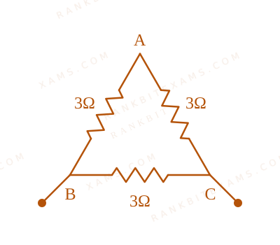
The total resistance of the continuous uniform wire loop is 9Ω. When bent into an equilateral triangle, it is split into three equal length sections. The resistance of each individual side is:

Rside = (9Ω)/(3) = 3Ω
Step 1: Calculating Equivalent Series and Parallel Resistance

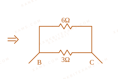
As shown in the circuit diagrams

Combination of Resistors diagram for Q23 - JEE Main 2025 Morning
and
Combination of Resistors diagram for Q23 - JEE Main 2025 Morning
, measuring across any two vertices means one branch contains a single side resistor (3Ω), while the other branch contains the remaining two sides connected in series :

Rₛₑᵣᵢₑₛ = 3Ω + 3Ω = 6Ω

Now, calculate the parallel equivalent between these two branches:

Req = Rside × RₛₑᵣᵢₑₛRside + Rₛₑᵣᵢₑₛ = (3 × 6)/(3 + 6) = (18)/(9) = 2Ω
Pattern Recognition

For a closed uniform loop with N equal sides, the parallel resistance measured across adjacent corners always simplifies to (N-1)/(N²) · Rtotal.

Chapter Mix

Class 12 Physics: Current Electricity

More Current Electricity Questions — jee_main_2025_28_jan_morning

Practice all Current Electricity previous-year questions →

Rankbit System
JEE Physics: Waves (+15.5%) | Electrostatics: Concentric Shells (-29.7%) | Modern Physics: Photoelectric Clones (+34.2%) | Mathematics: Definite Integrals (+18.1%) | Chemistry: Coordination Splitting (-11.4%) | JEE Physics: Waves (+15.5%) | Electrostatics: Concentric Shells (-29.7%) | Modern Physics: Photoelectric Clones (+34.2%) | Mathematics: Definite Integrals (+18.1%) | Chemistry: Coordination Splitting (-11.4%)