JEE Main · Physics → Steady

Current Electricity appeared 50 times across 3 years — 5.8% of Physics. This question is from Wheatstone Bridge.

Year 2026 2025 2024 Total
Questions 18 13 19 50

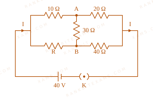
The value of current I in the electrical circuit as given below, when potential at A is equal to the potential at B, will be ________ A.
Wheatstone Bridge diagram for Q24 - JEE Main 2025 Evening
A bridge resistor network supplied by a 40V DC voltage source terminal layout.

Numerical Answer Type:
Enter a numerical value Answer: 2 +4 marks

Solution & Explanation

Related Formula

For a balanced Wheatstone bridge network, if the potentials at opposite nodes are equal (VA = VB), no current flows through the central branch. The resistance arms satisfy the balance ratio:

(R₁)/(R₂) = (R₃)/(R₄)

Total current from the source is calculated using Ohm's law:

I = VsourceRequivalent
Core Logic

Given conditions :

VA = VB Balanced condition

From the circuit network diagram [cite: 817, 818, 826, 828]:

  • Left-top arm = 10 Ω
  • Left-bottom arm = R
  • Right-top arm = 20 Ω
  • Right-bottom arm = 40 Ω
  • Apply the balance condition to solve for unknown resistor R :

(10)/(R) = (20)/(40) (10)/(R) = (1)/(2) R = 20 Ω [cite: 837, 838]

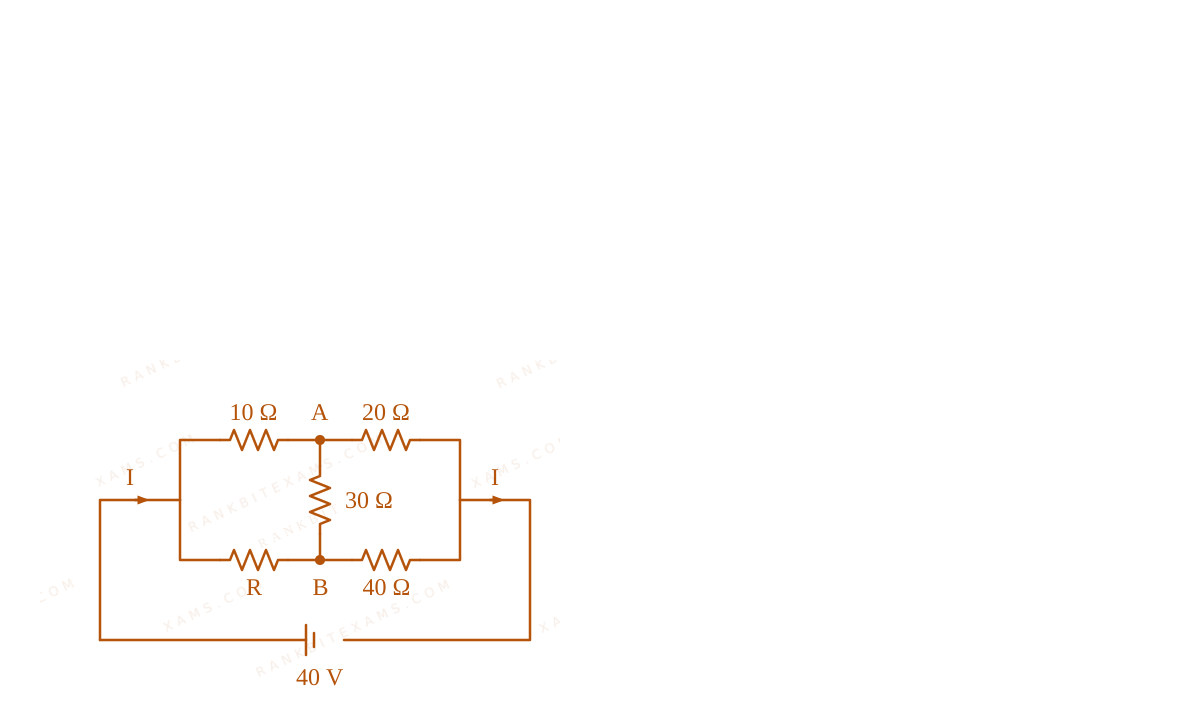
Now restructure the equivalent network : Since the central 30 Ω resistor branch carries zero current, it can be removed from the calculation [cite: 820, 834].

  • Top \parallel branch: 10 Ω + 20 Ω = 30 Ω
  • Bottom \parallel branch: 20 Ω + 40 Ω = 60 Ω
  • Calculate total equivalent resistance Req:

Req = (30 × 60)/(30 + 60) = (1800)/(90) = 20 Ω

Calculate total current I drawn from the 40V source:

I = 40 V20 Ω = 2 A
Step 1: Circuit Solution

The balanced bridge network layout with branch currents is shown below:

Wheatstone Bridge network reduction diagram for Q24
A bridge resistor network supplied by a 40V DC voltage source terminal layout.

Pattern Recognition

When a question states that two nodes are at equal potential (VA = VB), immediately identify it as a balanced Wheatstone bridge. This allows you to remove the central branch and simplify the circuit into basic series-\parallel resistor combinations.

Chapter Mix

Class 12 Physics: Current Electricity

Reference Study Guides

More Current Electricity Previous-Year Questions

Q jee_main_2026_21_jan_morning Heating Effect of Current
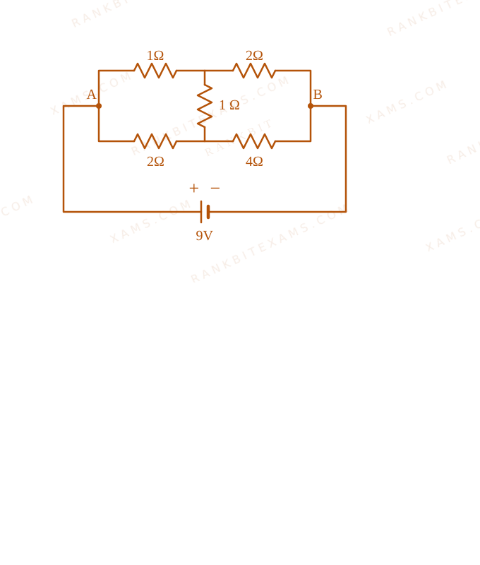
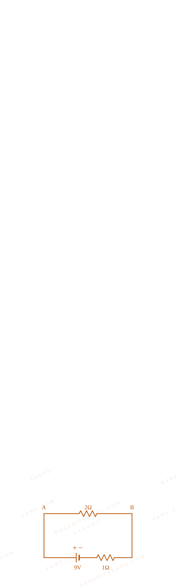
The heat generated in 1 minute between points A and B in the given circuit, when a battery of 9V with internal resistance of 1 Ω is connected across these points is ____ J.
Heating Effect of Current diagram for Q47 - JEE Main 2026 Morning
A bridge network with resistors 1 ohm, 2 ohms, 2 ohms, and 4 ohms forming the arms.
Numerical Answer. Answer: 1080 to 1080

Solution

Related Formula
Req = (R₁ R₂)/(R₁ + R₂) (parallel)

H = I² R t

I = VReq + r
Core Logic

The circuit is a balanced Wheatstone bridge between A and B, because the ratio of adjacent arms is (1)/(2) = (2)/(4). Thus, the middle 1 Ω resistor (if there is one connecting the middle nodes) is ineffective.
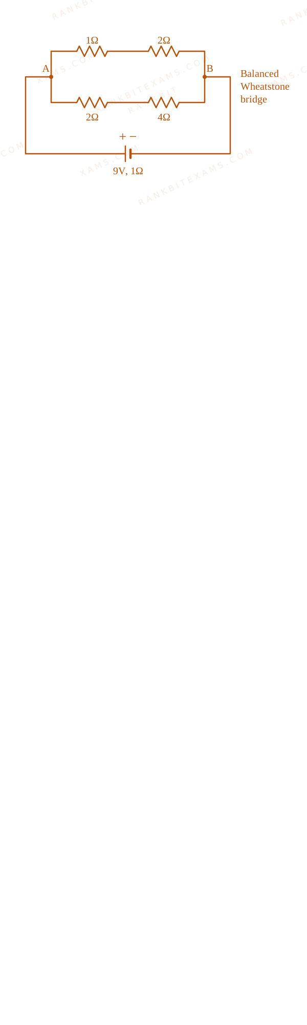
Heating Effect of Current solution diagram for Q47 - JEE Main 2026 Morning
A bridge network with resistors 1 ohm, 2 ohms, 2 ohms, and 4 ohms forming the arms.

The equivalent resistance across AB (RAB) involves the upper branch (1+2 = 3 Ω) and the lower branch (2+4 = 6 Ω) in parallel.
Heating Effect of Current solution diagram for Q47 - JEE Main 2026 Morning
A bridge network with resistors 1 ohm, 2 ohms, 2 ohms, and 4 ohms forming the arms.

RAB = (3 × 6)/(3 + 6) = (18)/(9) = 2 Ω
Step 1: Calculate Current and Heat

Total resistance in the circuit = RAB + rinternal = 2 + 1 = 3 Ω. Total current from the battery i = 9V3 Ω = 3A.

The heat generated specifically between points A and B in 1 minute (60 seconds) is:

HAB = i² RAB t = (3)² × 2 × 60 HAB = 9 × 120 = 1080 J
Pattern Recognition

Check for balanced Wheatstone bridge first. Then use H = i² R t strictly with the equivalent resistance of just the section AB to find heat specifically generated across AB.

Chapter Mix

Class 12 Physics: Current Electricity
Q28 jee_main_2026_21_jan_evening Potentiometer
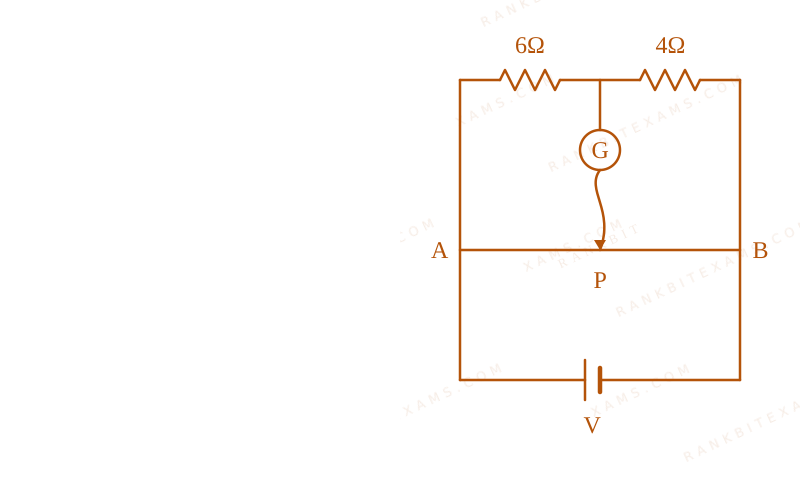
The total length of potentiometer wire AB is 50 cm in the arrangement as shown in figure. If P is the point where the galvanometer shows zero reading then the length AP is ________ cm.
Potentiometer diagram for Q28 - JEE Main 2026 Evening
Potentiometer circuit with a 50 cm wire AB, a galvanometer, and standard bridge resistors of 6 ohms and 4 ohms.
  • A. 15
  • B. 30
  • C. 25
  • D. 20

Solution

Related Formula

For a balanced Wheatstone bridge configuration:

(R₁)/(R₂) = (l₁)/(l₂)
Core Logic

When the galvanometer shows zero reading, it implies that the bridge is balanced. The resistance of the wire segments is proportional to their lengths.

Let the length of segment AP be lAP and PB be lPB.

6 ΩRAP = 4 ΩRPB

Since R ∝ l:

RAPRPB = lAPlPB = (6)/(4) = (3)/(2)
Step 1: Applying Total Length Constraint

We are given the total length:

lAP + lPB = 50 cm

Using the ratio lAP = (3)/(2) lPB:

(3)/(2)lPB + lPB = 50 (5)/(2)lPB = 50 lPB = 20 cm
Step 2: Final Conclusion

Solving for lAP:

lAP = 50 - 20 = 30 cm

Alternatively, lAP = (3)/(3+2) × 50 = (3)/(5) × 50 = 30 cm.

Pattern Recognition

Null deflection over a uniform wire directly translates resistance ratios into length ratios. Standard Wheatstone bridge application wrapped in potentiometer geometry.

Chapter Mix

Class 12 Physics: Current Electricity
Q35 jee_main_2026_21_jan_evening Maximum Power Transfer Theorem
A battery with EMF E and internal resistance r is connected across a resistance R. The power consumption in R will be maximum when :
  • A. R=2r
  • B. R=(r)/(2)
  • C. R=√(2)r
  • D. R=r

Solution

Related Formula
P = I² R = ((E)/(R+r))² R
Core Logic

To maximize power across the load resistance R, we apply the Maximum Power Transfer Theorem. The power transferred to the load is maximum when the load resistance equals the internal resistance of the battery.

Setting (dP)/(dR) = 0 yields: R = r

Step 1: Final Conclusion

Power is maximum when the external resistance is strictly equal to the internal resistance (R=r).

Pattern Recognition

Direct theoretical application of the Maximum Power Transfer Theorem.

Chapter Mix

Class 12 Physics: Current Electricity
Q40 jee_main_2026_21_jan_evening Combination of Resistors
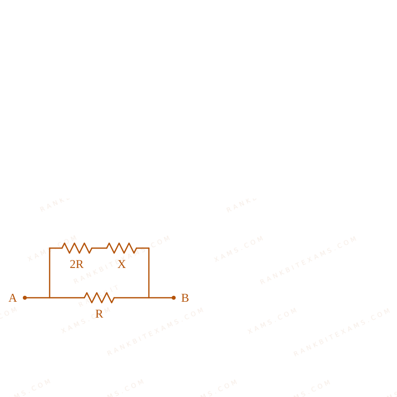
Two known resistance of R Ω and 2R Ω and one unknown resistance X Ω are connected in a circuit as shown in the figure. If the equivalent resistance between points A and B in the circuit is X Ω, then the value of X is ________ Ω.
Circuit diagram of resistors for Q40 - JEE Main 2026 Evening
Bridge-like resistor circuit containing unknown resistance X and known resistances R and 2R.
  • A. (√(3)-1)R
  • B. R
  • C. 2(√(3)-1)R
  • D. (√(3)+1)R

Solution

Related Formula

For parallel combination: Req = (R₁ R₂)/(R₁ + R₂) For series combination: Req = R₁ + R₂

Core Logic

Based on the circuit topology, the 2R and X resistors are in series. This combination is in parallel with the R resistor. The total equivalent resistance across A and B is given as X.

Req = ((2R + X) · (R))/((2R + X) + R)
Step 1: Setting up the Quadratic

Set the equivalent resistance equal to X:

X = ((2R + X)R)/(3R + X)

Cross-multiplying yields:

X(3R + X) = 2R² + XR 3RX + X² = 2R² + XR X² + 2RX - 2R² = 0
Step 2: Solving for X

Using the quadratic formula to solve for X:

X = -2R ± √((2R)² - 4(1)(-2R²))2 X = -2R ± √(4R² + 8R²)2 = -2R ± √(12R²)2 X = -2R ± 2R√(3)2 = -R ± R√(3)

Since resistance must be positive:

X = (√(3) - 1)R
Pattern Recognition

Self-referential equivalent resistance problems always collapse into a quadratic equation x² + ax + b = 0. Solve strictly for the positive root.

Chapter Mix

Class 12 Physics: Current Electricity
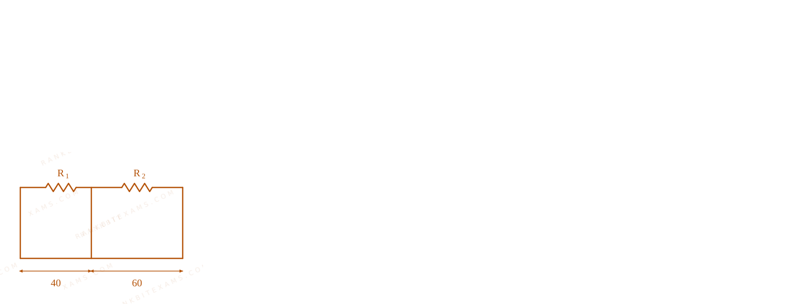
Q31 jee_main_2026_22_january_morning Meter Bridge
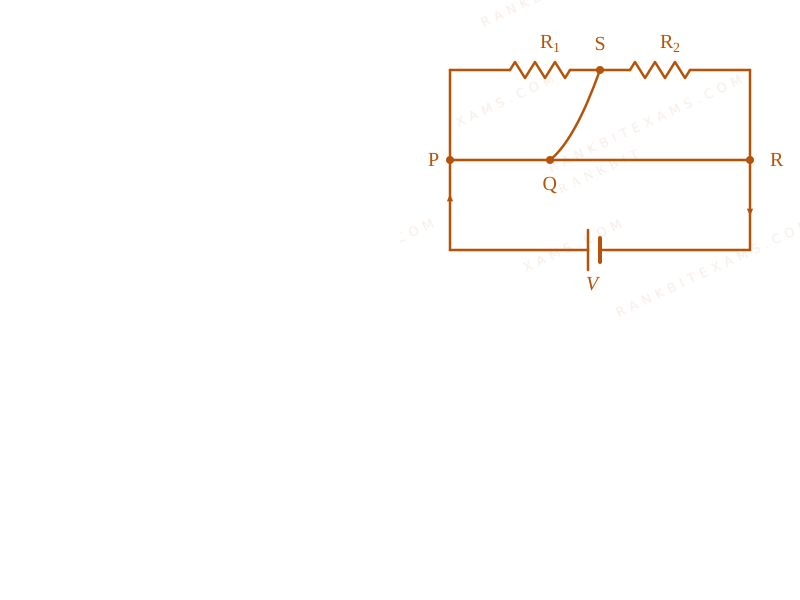
A meter bridge with two resistances R₁ and R₂ as shown in figure was balanced (null point) at 40 cm from the point P. The null point changed to 50 cm from the point P, when 16~Ω resistance is connected in parallel to R₂. The values of resistances R₁ and R₂ are \_\_\_\_.
Current Electricity diagram for Q31 - JEE Main 2026 January Morning
Meter bridge circuit with resistances R1 and R2 and balancing lengths.
  • A. R₂ = 16Ω, R₁ = (16)/(3)Ω
  • B. R₂ = 4Ω, R₁ = (4)/(3)Ω
  • C. R₂ = 8Ω, R₁ = (16)/(3)Ω
  • D. R₂ = 12Ω, R₁ = (12)/(3)Ω

Solution

Related Formula
(R₁)/(R₂) = (l₁)/(100 - l₁)
Core Logic

Solution diagram for Q31 - JEE Main 2026 Morning
Meter bridge circuit with resistances R1 and R2 and balancing lengths.

Initially:

(R₁)/(R₂) = (40)/(60) = (2)/(3) R₁ = (2)/(3)R₂ ---- (1)

After connecting 16~Ω in parallel with R₂:

(R₁)/(((R₂ × 16)/(R₂ + 16))) = (50)/(50) R₁ = (16 R₂)/(16 + R₂) ---- (2)

Solving equations (1) and (2) yields:

R₂ = 8~Ω, R₁ = (16)/(3)~Ω
Pattern Recognition

Sees: Meter bridge balancing with parallel shunt resistance. Shortcut: Set up length ratios for initial and modified states and solve linear simultaneous equations. Check: Matches option (3). ✓

Chapter Mix

Class 12 Physics: Current Electricity

More Current Electricity Questions — jee_main_2025_28_jan_evening

Practice all Current Electricity previous-year questions →

Rankbit System
JEE Physics: Waves (+15.5%) | Electrostatics: Concentric Shells (-29.7%) | Modern Physics: Photoelectric Clones (+34.2%) | Mathematics: Definite Integrals (+18.1%) | Chemistry: Coordination Splitting (-11.4%) | JEE Physics: Waves (+15.5%) | Electrostatics: Concentric Shells (-29.7%) | Modern Physics: Photoelectric Clones (+34.2%) | Mathematics: Definite Integrals (+18.1%) | Chemistry: Coordination Splitting (-11.4%)