A wire of resistance R$R$ is bent into an equilateral triangle and an identical wire is bent into a square. The ratio of resistance between the two end points of an edge of the triangle to that of the square is
A.9 / 8$9 / 8$
B.8 / 9$8 / 9$
C.27/32
D.32/27
Solution & Explanation
Related Formula
R = ρ A R ∝$$\mathrm{R} = \frac{\rho\ell}{\mathrm{A}} \implies \mathrm{R} \propto \ell$$
Core Logic
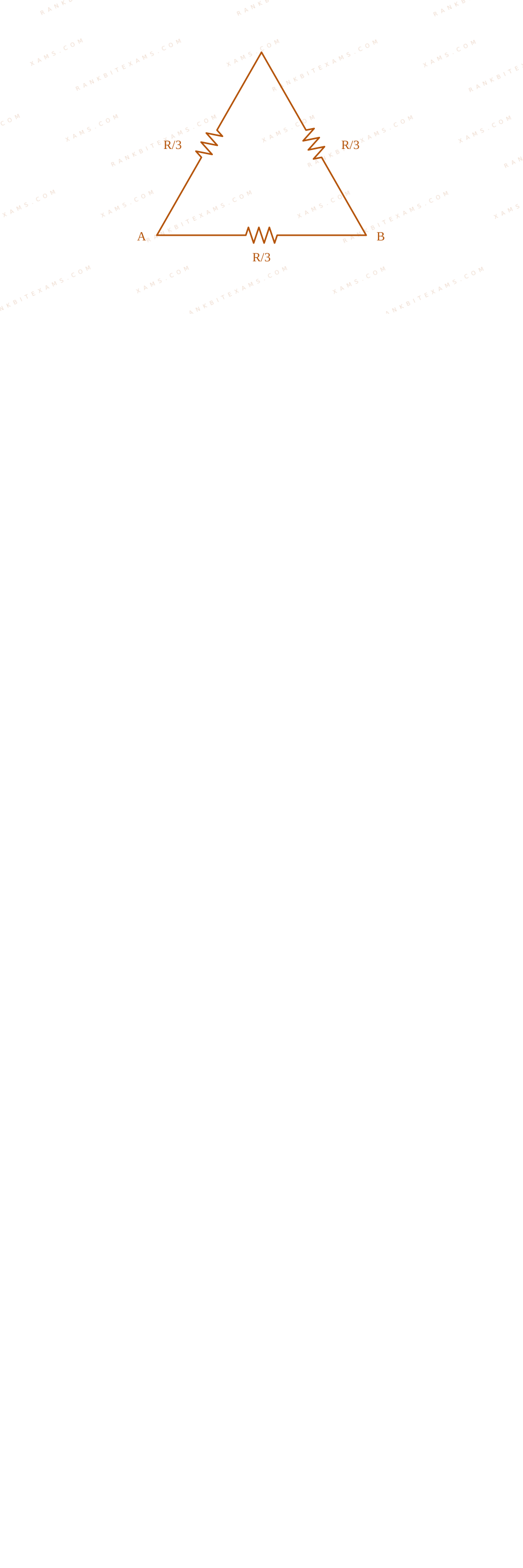
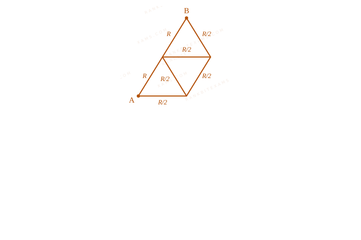
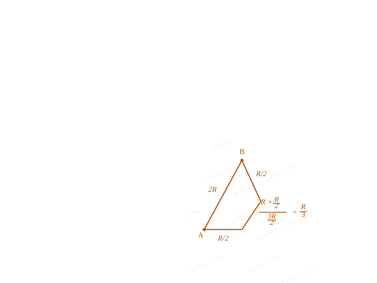
For the equilateral triangle, the total resistance R$\mathrm{R}$ is divided into three equal line parts of value R3$\frac{\mathrm{R}}{3}$ each:
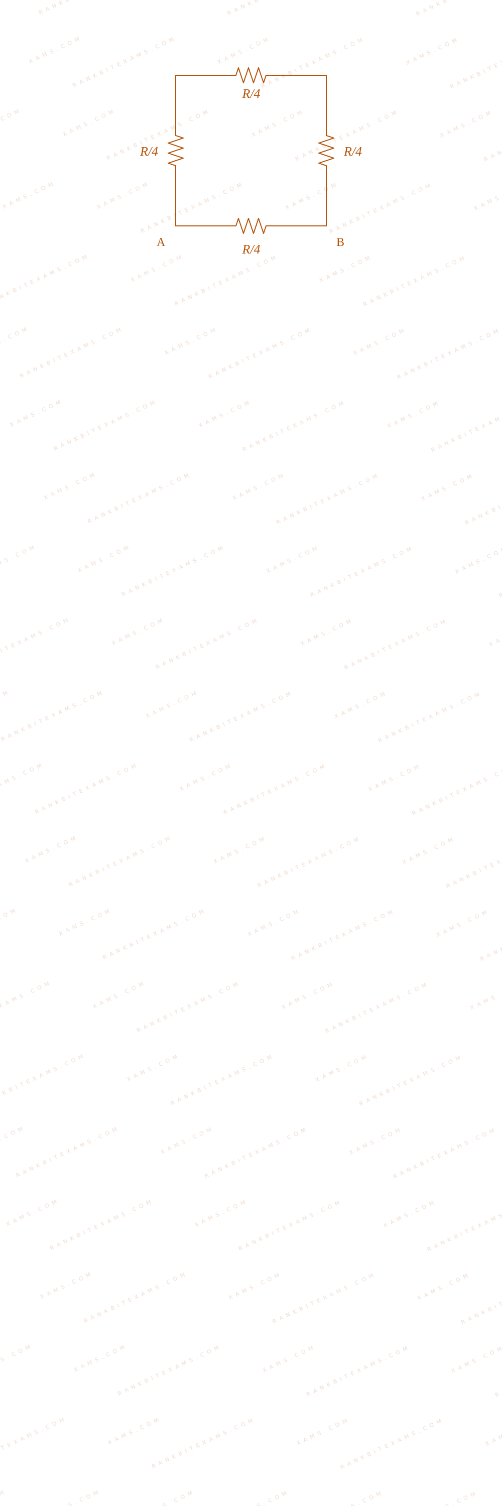
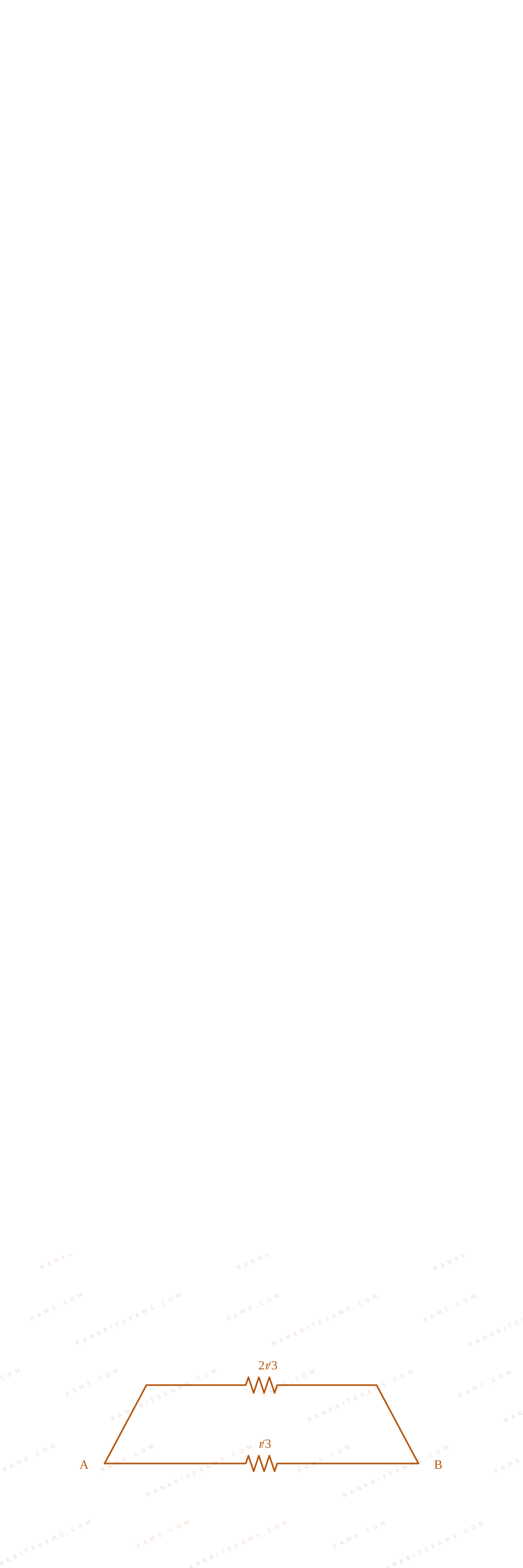
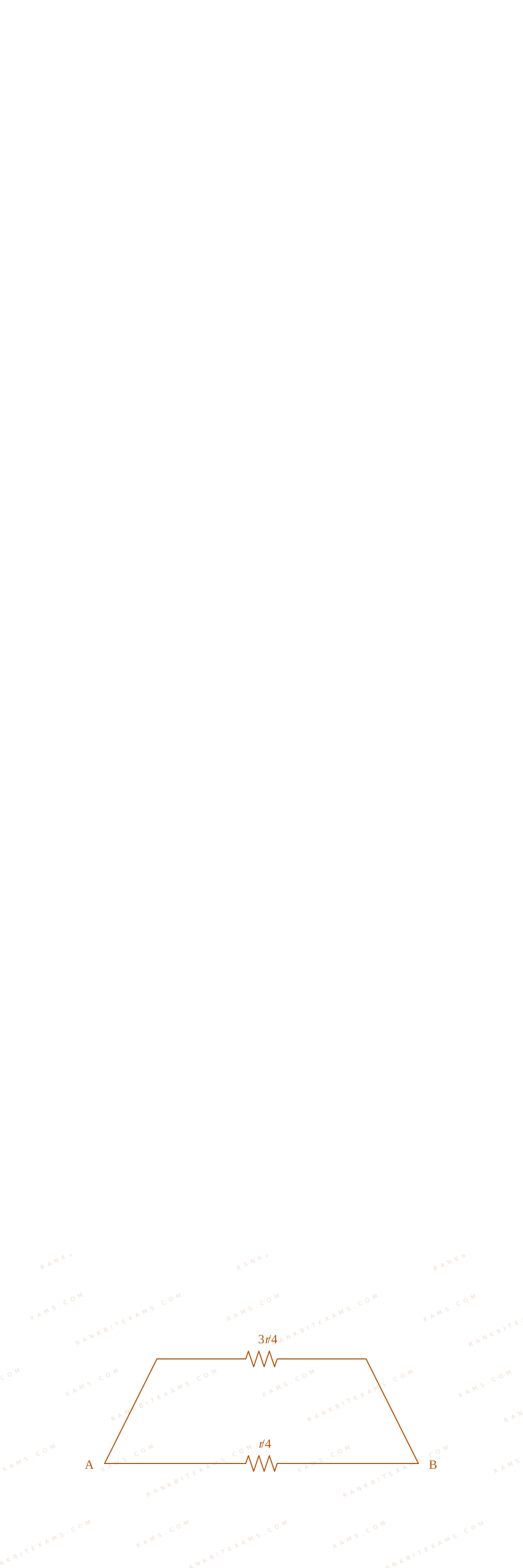
Visual representation of triangle and square edge divisions for Q15
Visual representation of triangle and square edge divisions for Q15
An edge configuration places one part in parallel with the other two series steps:
For a regular polygon with N$\mathrm{N}$ identical sides formed from a wire of resistance R$\mathrm{R}$, the resistance across one edge is always given by (N-1)N²R$\frac{(\mathrm{N}-1)}{\mathrm{N}^2}\mathrm{R}$.
Keywords:#wire bent into equilateral triangle and square#JEE Main 2025 Morning Q15#Current Electricity JEE Main 2025#Combination of Resistors JEE Main 2025
More Current Electricity Previous-Year Questions — Page 3
Q37jee_main_2026_24_january_morningMeter Bridge
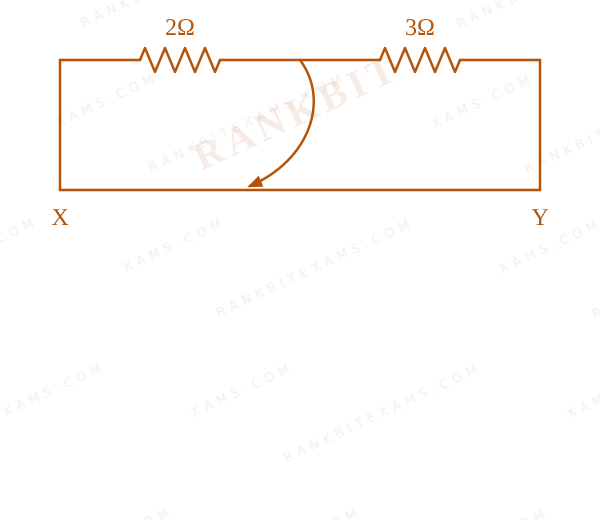
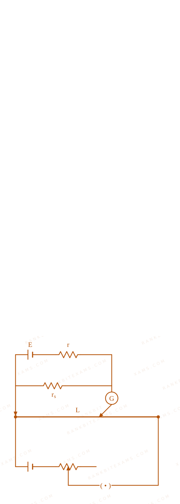
Two resistors 2Ω$2\Omega$ and 3Ω$3\Omega$ are connected in the gaps of bridge as shown in figure. The null point is obtained with the contact of jockey at some point on wire XY. When an unknown resistor is connected in parallel with 3Ω$3\Omega$ resistor, the null point is shifted by 22.5 cm toward Y. The resistance of unknown resistor is ____ Ω$\Omega$.
Meter bridge with 2 ohm and 3 ohm resistors connected in gaps.
When an unknown resistor R$R$ is connected in parallel with 3 Ω$3\, \Omega$, the new resistance in the right gap is R' = (3R)/(3 + R)$R' = \frac{3R}{3 + R}$.
The null point shifts by 22.5 cm$22.5 \text{ cm}$ towards Y, so the new balancing length is x' = 40 + 22.5 = 62.5 cm$x' = 40 + 22.5 = 62.5 \text{ cm}$.
The new balance equation is:
A shift 'towards Y' means the balance point moved right, which implies the right gap resistance decreased. Connecting in parallel correctly decreases resistance.
Chapter Mix
Class 12 Physics: Current Electricity
Q26jee_main_2026_24_january_eveningDC Circuits and Ammeters
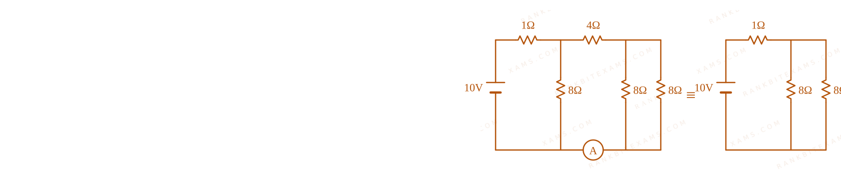
The reading of the ammeter (A) in steady state in the following circuit (assuming negligible internal resistance of the ammeter) is ____ A.
A circuit diagram containing a 10V battery, multiple resistors, a 10 microfarad capacitor, and an ammeter.
A.2$2$
B.1$1$
C.1 / 2$1 / 2$
D.0$0$
Solution
Core Logic
In steady state, the capacitor acts as an open circuit. No current flows through the branch containing the 10$10\mu\text{F}$ capacitor.
A circuit diagram containing a 10V battery, multiple resistors, a 10 microfarad capacitor, and an ammeter.
After removing the capacitor branch, we simplify the network of resistors.
Step 1: Equivalent Resistance
I = 2A$$\mathrm{I} = 2\mathrm{A}$$
A circuit diagram containing a 10V battery, multiple resistors, a 10 microfarad capacitor, and an ammeter.
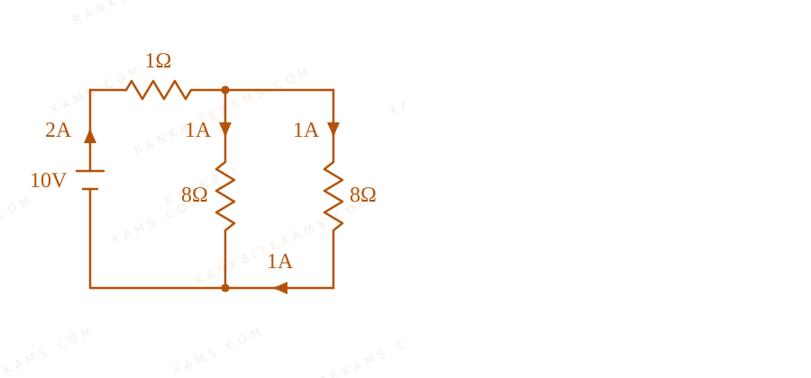
By further simplifying the parallel and series combinations, we determine the main current and the current branching into the ammeter.
Step 2: Ammeter Reading
The current of 2A$2\mathrm{A}$ splits equally through the symmetrical 8Ω$8\Omega$ branches.
The ammeter reading is 1A$1\mathrm{A}$.
Pattern Recognition
Steady state DC + Capacitor = Open circuit. Always delete the capacitor branch first before calculating equivalent resistance.
Chapter Mix
Class 12 Physics: Current Electricity
Class 12 Physics: Electrostatics
Q29jee_main_2026_24_january_eveningResistor Networks and Symmetry
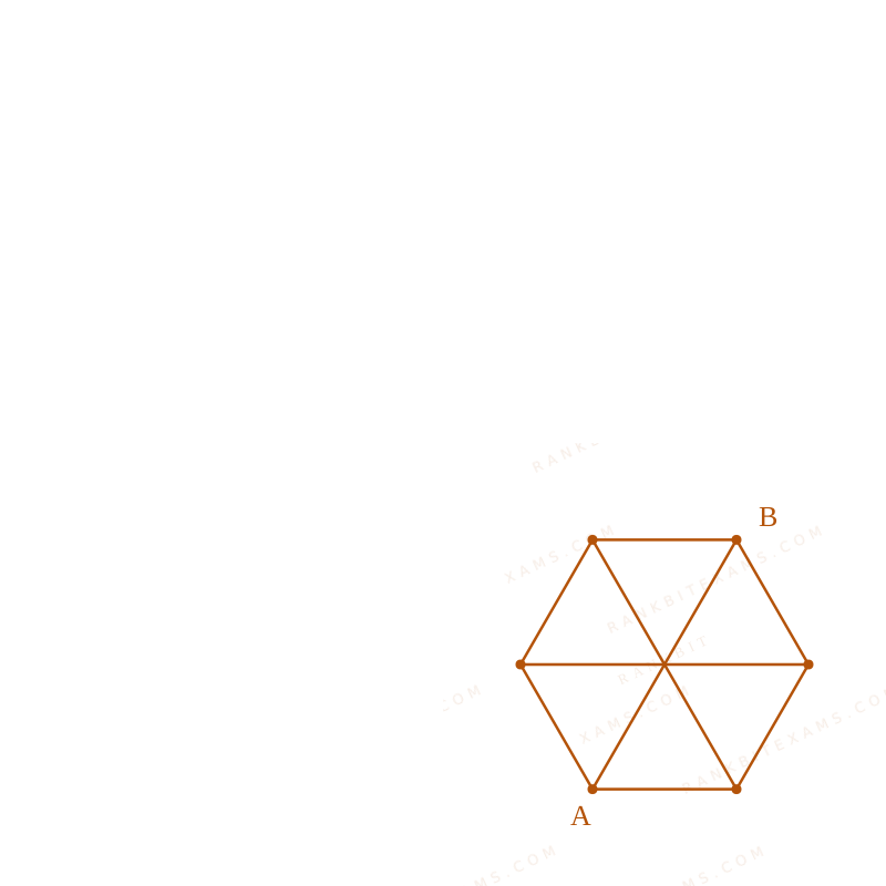
A regular hexagon is formed by six wires each of resistance r Ω$\Omega$ and the corners are joined to centre by wires of same resistance. If the current enters at one corner and leaves at the opposite corner, the equivalent resistance of the hexagon between the two opposite corners will be
A.(4)/(5)r$\frac{4}{5}r$
B.(5)/(8)r$\frac{5}{8}r$
C.(3)/(4)r$\frac{3}{4}r$
D.(3)/(5)r$\frac{3}{5}r$
Solution
Core Logic
By applying the principle of symmetry to the regular hexagonal resistor network, the circuit can be simplified across the axis of symmetry.
Resistor Networks and Symmetry diagram for Q29 - JEE Main 2026 Evening
Resistor Networks and Symmetry diagram for Q29 - JEE Main 2026 Evening
Step 1: Network Reduction
Using equipotential nodes along the perpendicular bisector, we can resolve the network into parallel and series components.
Resistor Networks and Symmetry diagram for Q29 - JEE Main 2026 Evening
The equivalent resistance for each half is determined as follows:
For regular polygonal networks with central connections, always search for a line of equipotential symmetry perpendicular to the line joining the input and output nodes. Nodes on this axis can be detached or merged.
Chapter Mix
Class 12 Physics: Current Electricity
Q48jee_main_2026_24_january_eveningMeter Bridge
In a meter bridge experiment to determine the value of unknown resistance, first the resistances 2 Ω$2 \Omega$ and 3 Ω$3 \Omega$ are connected in the left and right gaps of the bridge and the null point is obtained at a distance l cm from the left. Now when an unknown resistance x Ω$\Omega$ is connected in parallel to 3 Ω$3 \Omega$ resistance, the null point is shifted by 10 cm to the right of wire. The value of unknown resistance x is ____ Ω$\Omega$ .
In Case II, the right gap resistance becomes a parallel combination: R' = (3x)/(3+x)$R' = \frac{3x}{3+x}$.
The new null point is shifted 10 cm$10 \text{ cm}$ to the right, meaning the new balancing length is ' = 40 + 10 = 50 cm$\ell' = 40 + 10 = 50 \text{ cm}$.
If the null point falls exactly at 50 cm$50 \text{ cm}$, the two gap resistances must be identical. Recognizing this immediately yields Rparallel = 2$R_{\text{parallel}} = 2$ without solving proportional fractions.
Chapter Mix
Class 12 Physics: Current Electricity
Q28jee_main_2026_28_january_morningPotentiometer
In the potentiometer, when the cell in the secondary circuit is shunted with 4 Ω$4 \,\Omega$ resistance, the balance is obtained at the length 120 cm of wire. Now when the same cell in shunted with 12 Ω$12 \,\Omega$ resistance, the balance is shifted to a length of 180 cm. The internal resistance of cell is ____ Ω$\Omega$.
A.3$3$
B.4$4$
C.12$12$
D.6$6$
Solution
Related Formula
For a cell of emf E$E$ and internal resistance r$r$ shunted by a resistance R$R$, the terminal voltage is:
V = (E · R)/(r + R)$$V = \frac{E \cdot R}{r + R}$$
In a potentiometer, the terminal voltage is proportional to the balancing length l$l$:
V = K · l$V = K \cdot l$
Core Logic
Equate the expressions for terminal voltage for both cases to their respective balancing lengths. Let E$E$ be the emf and r$r$ be the internal resistance of the cell.
Standard potentiometer problem. Ratio of balancing lengths maps directly to the ratio of terminal voltages. (l₁)/(l₂) = (R₁(r+R₂))/(R₂(r+R₁))$\frac{l_1}{l_2} = \frac{R_1(r+R_2)}{R_2(r+R_1)}$. Plugging the values simplifies it instantly.
Chapter Mix
Class 12 Physics: Current Electricity
More Current Electricity Questions — jee_main_2025_28_jan_morning
Practice past-year questions one chapter at a time. Pick an exam → subject → chapter and get every PYQ for that topic — pulled together from all past papers — with the chapter's key formulas alongside.