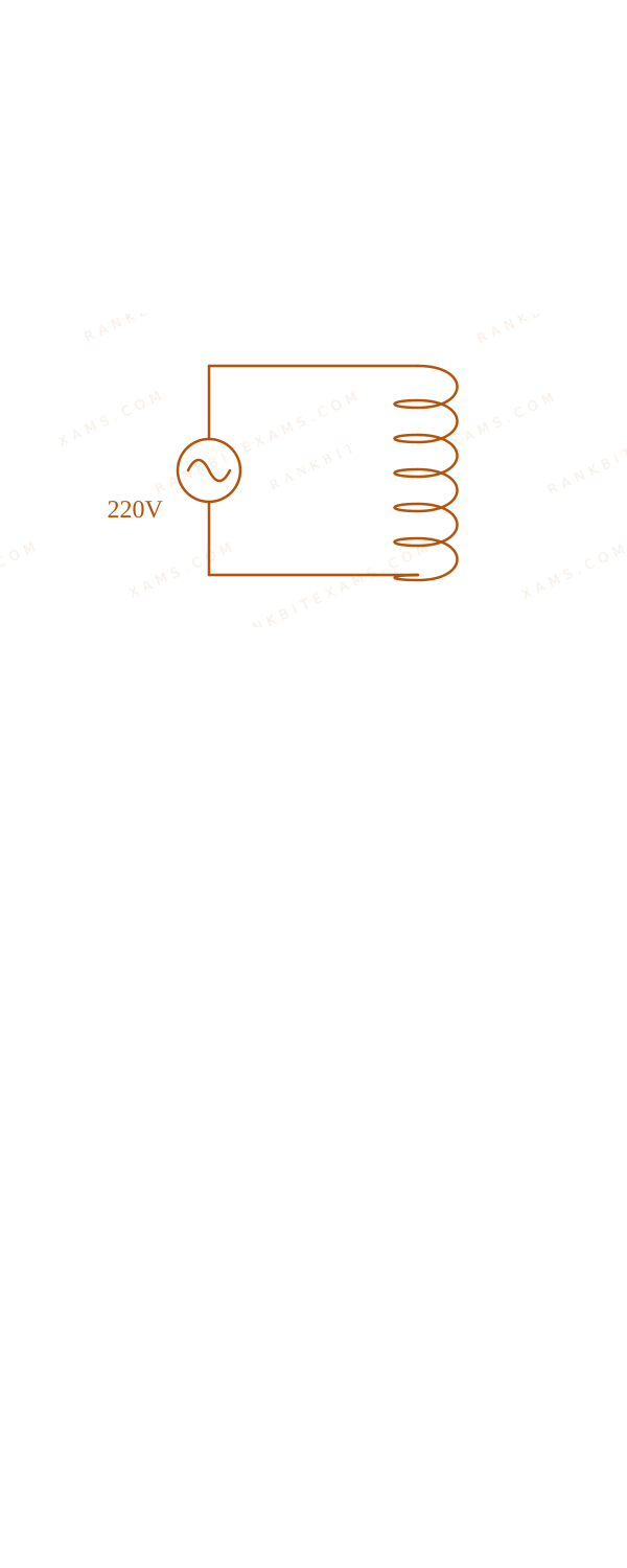
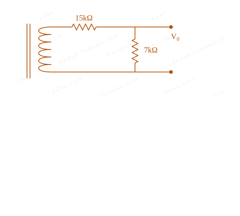
Primary coil of a transformer is connected to 220V$220\mathrm{V}$ ac. Primary and secondary turns of the transforms are 100 and 10 respectively. Secondary coil of transformer is connected to two series resistance shown in shown in figure. Circuit containing a transformer supplying a secondary series resistor network to tap output voltage. The output voltage (V₀)$(V_0)$ is: Circuit containing a transformer supplying a secondary series resistor network to tap output voltage.
A.7 ~V$7 \mathrm{~V}$
B.15 ~V$15 \mathrm{~V}$
C.44 ~V$44 \mathrm{~V}$
D.22 ~V$22 \mathrm{~V}$
Solution & Explanation
Related Formula
(ε₁)/(ε₂) = (N₁)/(N₂)$$\frac{\varepsilon_1}{\varepsilon_2} = \frac{N_1}{N_2}$$V₀ = I · Rₜₐₚ$$V_0 = I \cdot R_{\text{tap}}$$
Core Logic
First, evaluate the secondary voltage induced by the transformer using the turns ratio. Then, apply basic DC voltage divider (or Ohm's law) logic to the secondary circuit to find the voltage drop V₀$V_0$ across the specific tapped resistance.
The secondary circuit contains two resistors in series (e.g., 15 ~kΩ$15 \mathrm{~k\Omega}$ and 7 ~kΩ$7 \mathrm{~k\Omega}$ forming 22 ~kΩ$22 \mathrm{~k\Omega}$ total, based on standard circuit values extracted from problem context).
Current in secondary:
Keywords:#Transformers#JEE Main 2024 Morning Q41#Alternating Current JEE Main 2024#Secondary voltage#Transformer coil#AC source#Output voltage#Series resistance
More Alternating Current Previous-Year Questions — Page 2
Qjee_main_2025_07_april_morningAc Circuits
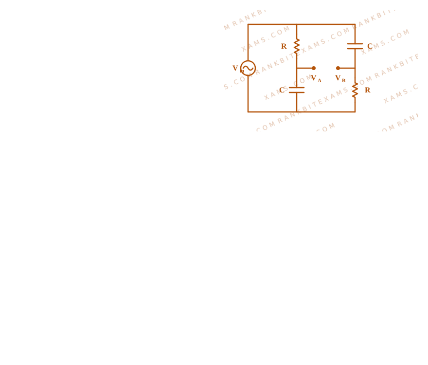
For ac circuit shown in figure, R = 100 kΩ$R = 100 \, \text{k}\Omega$ and C = 100 pF$C = 100 \, \text{pF}$ and the phase difference between Vᵢₙ$V_{\text{in}}$ and (VB - VA)$(V_{\text{B}} - V_{\text{A}})$ is 90^°$90^\circ$ . The input signal frequency is 10x$10^{\text{x}}$ rad/sec, where 'x' is An AC bridge circuit with input voltage connected across symmetrically crossed pairs of 100 kOhm resistors and 100 pF capacitors.
Numerical Answer.Answer: 5 to 5
Solution
Related Formula
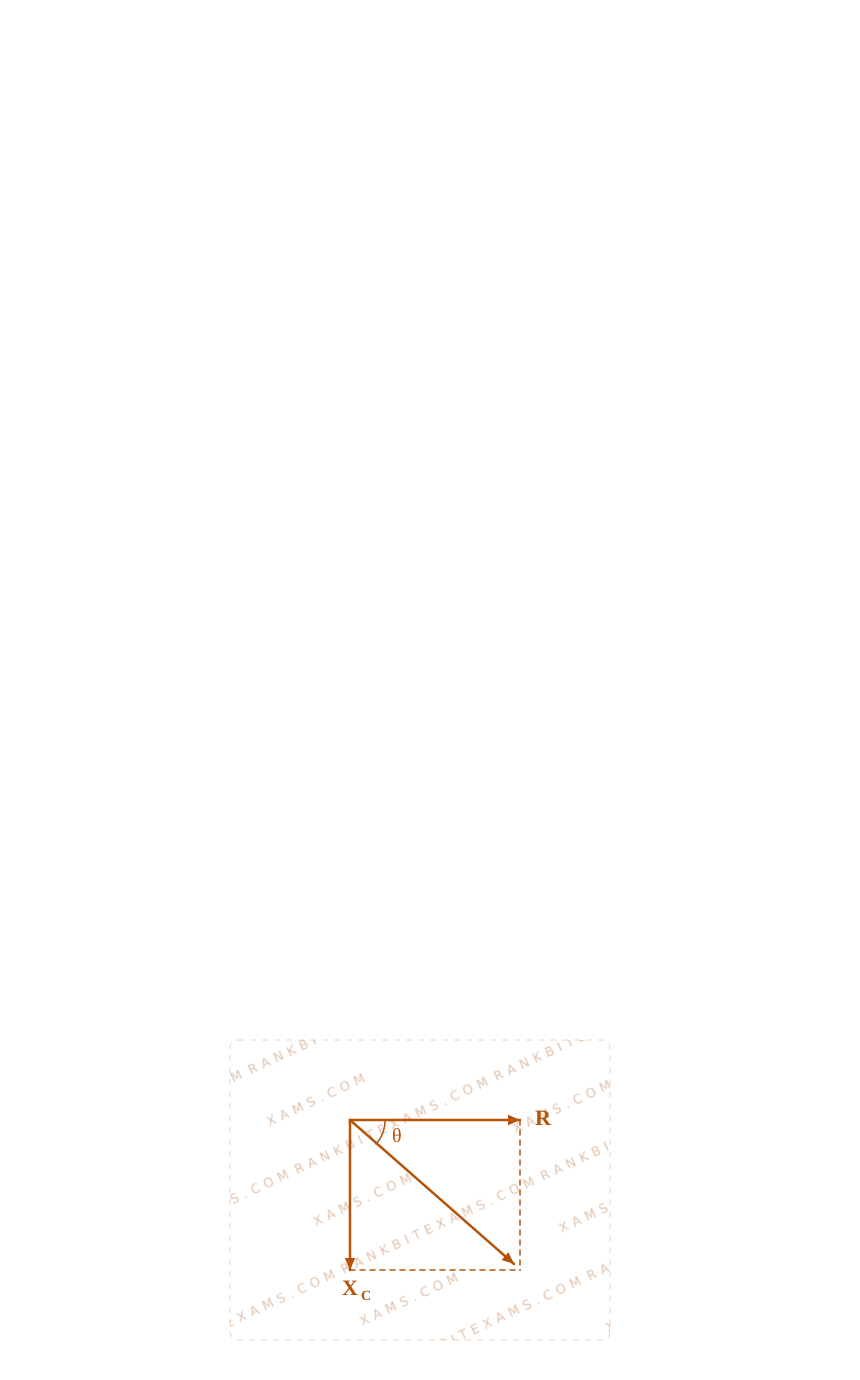
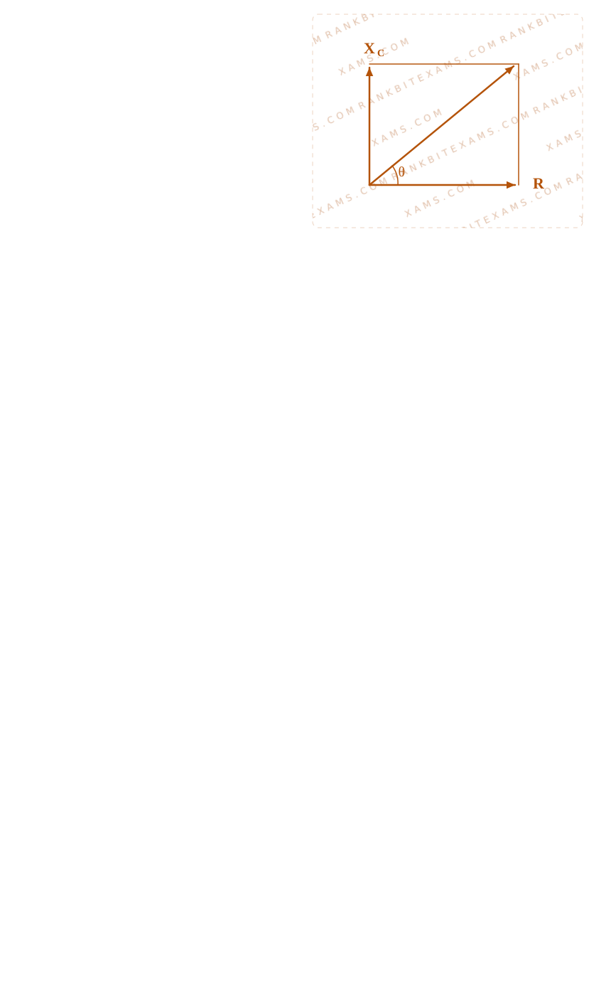
For a series RC branch, the voltage phase angle θ$\theta$ is:
θ = (XC)/(R) = (1)/(ω C R)$$\tan\theta = \frac{X_C}{R} = \frac{1}{\omega C R}$$
If the phase difference between Vᵢₙ$V_{\text{in}}$ and (VB - VA)$(V_B - V_A)$ is 90^°$90^\circ$:
An AC bridge circuit with input voltage connected across symmetrically crossed pairs of 100 kOhm resistors and 100 pF capacitors.An AC bridge circuit with input voltage connected across symmetrically crossed pairs of 100 kOhm resistors and 100 pF capacitors.
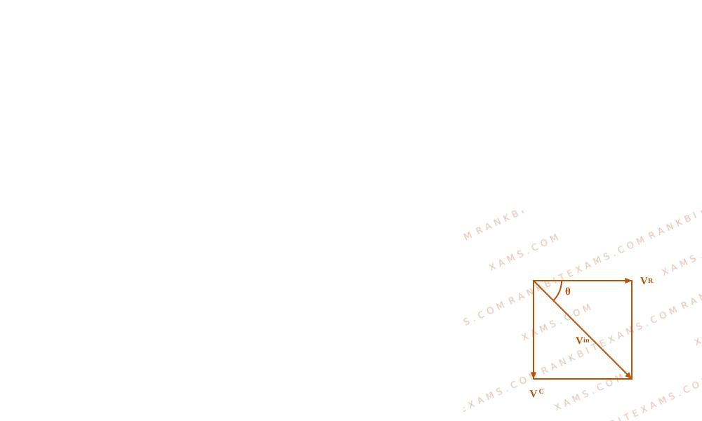
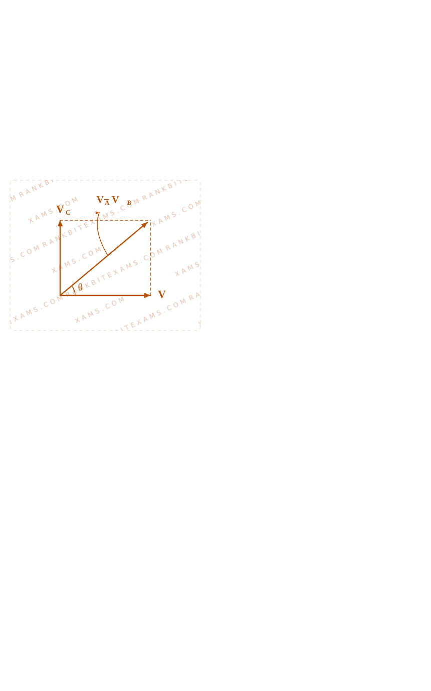
From the phasor representation of the symmetric RC divider bridge:
The phase angle of VA$V_A$ is θ$\theta$ behind the input voltage.
The phase angle of VB$V_B$ is 90^° - θ$90^\circ - \theta$ ahead of the input.
If their combined relative phase difference is 90^°$90^\circ$, this symmetry dictates:
An AC bridge circuit with input voltage connected across symmetrically crossed pairs of 100 kOhm resistors and 100 pF capacitors.An AC bridge circuit with input voltage connected across symmetrically crossed pairs of 100 kOhm resistors and 100 pF capacitors.
Since ω = 10^x$\omega = 10^x$, we get x = 5$x = 5$.
Pattern Recognition
Sees: Phase shift of 90^°$90^\circ$ across a symmetric RC bridge.
Shortcut: Clamping phase shift at 90^°$90^\circ$ implies the reactive impedance equals the resistive impedance (XC = R$X_C = R$). The frequency is simply the characteristic time constant frequency ω = 1/τ = 1/(RC)$\omega = 1/\tau = 1/(RC)$.
Chapter Mix
Class 12 Physics: Alternating Current
Q9jee_main_2025_07_april_morningRms Value of Current
An ac current is represented as
i = 5 √(2) + 1 0 (6 5 0 π t + (π)/(6)) A m p$$i = 5 \sqrt {2} + 1 0 \cos \left(6 5 0 \pi t + \frac {\pi}{6}\right) \mathrm {A m p}$$
The r.m.s value of the current is
A. 50 Amp
B.100Amp$100\mathrm{Amp}$
C. 10 Amp
D.5 √(2) Amp$5 \sqrt{2} \mathrm{Amp}$
Solution
Related Formula
For a current having both DC and AC components i = Idc + I₀ (ω t + φ)$i = I_{\text{dc}} + I_0 \cos(\omega t + \phi)$, the mean-square value is:
Sees: Superposition of a DC current Idc$I_{\text{dc}}$ and a pure AC cosine wave with amplitude Iac$I_{\text{ac}}$.
Shortcut: Use the orthogonal component RMS formula: Irms = Idc² + Iac,rms²$I_{\text{rms}} = \sqrt{I_{\text{dc}}^2 + I_{\text{ac,rms}}^2}$. Here Idc = 5√(2)$I_{\text{dc}} = 5\sqrt{2}$ and Iac,rms = 10/√(2) = 5√(2)$I_{\text{ac,rms}} = 10/\sqrt{2} = 5\sqrt{2}$. Thus, Irms = √(50 + 50) = 10 ~A$I_{\text{rms}} = \sqrt{50 + 50} = 10 \mathrm{~A}$.
Chapter Mix
Class 12 Physics: Alternating Current
Q25jee_main_2025_04_april_eveningAC Circuit with R and L
When inductive reactance equals resistance (XL = R$X_L = R$), the impedance is exactly R√(2)$R\sqrt{2}$. The factor of √(2)$\sqrt{2}$ in the denominator cancels perfectly with the peak current conversion multiplier.
Chapter Mix
Class 12 Physics: Alternating Current
Qjee_main_2025_04_april_morningRMS Current and Frequency
An alternating current is represented by the equation, i=100√(2) (100π t)$i=100\sqrt{2}\sin(100\pi t)$ ampere. The RMS value of current and the frequency of the given alternating current are
Doubling the denominator of an inversely proportional relationship halves the primary value, yielding an absolute 50%$50\%$ decrease.
Chapter Mix
Class 12 Physics: Wave Optics
Q22jee_main_2025_07_april_eveningAC Circuits with LCR
An inductor of reactance 100Ω$100\Omega$, a capacitor of reactance 50Ω$50\Omega$, and a resistor of resistance 50Ω$50\Omega$ are connected in series with an AC source of 10~V$10\mathrm{~V}$, 50~Hz$50\mathrm{~Hz}$. Average power dissipated by the circuit is ______ W. [cite: 185, 186]
Remember that only the resistive element dissipates real thermal power over a complete cycle[cite: 784, 785]. Reactive elements like ideal inductors and capacitors store and release energy alternately without net consumption.
Chapter Mix
Class 12 Physics: Alternating Current
More Alternating Current Questions — jee_main_2024_30_jan_morning
Practice past-year questions one chapter at a time. Pick an exam → subject → chapter and get every PYQ for that topic — pulled together from all past papers — with the chapter's key formulas alongside.