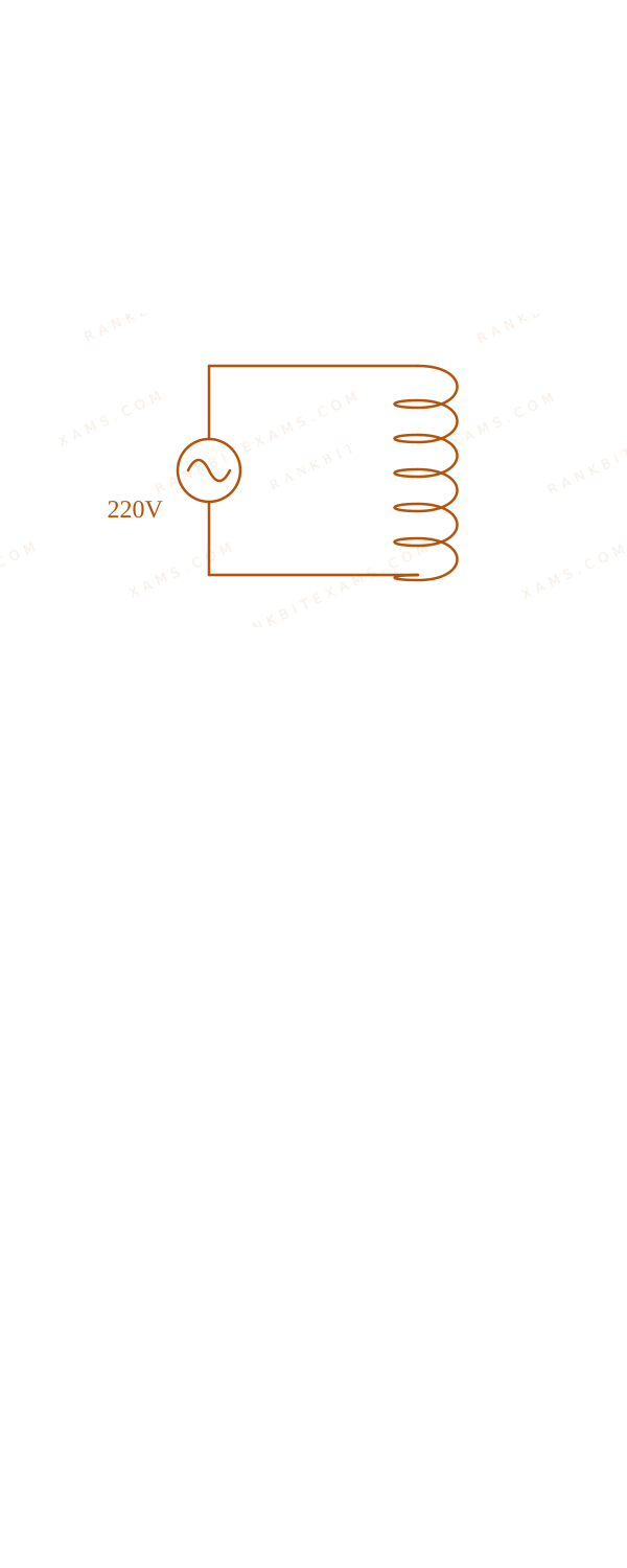
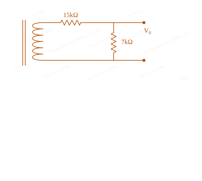
Primary coil of a transformer is connected to 220V$220\mathrm{V}$ ac. Primary and secondary turns of the transforms are 100 and 10 respectively. Secondary coil of transformer is connected to two series resistance shown in shown in figure. Circuit containing a transformer supplying a secondary series resistor network to tap output voltage. The output voltage (V₀)$(V_0)$ is: Circuit containing a transformer supplying a secondary series resistor network to tap output voltage.
A.7 ~V$7 \mathrm{~V}$
B.15 ~V$15 \mathrm{~V}$
C.44 ~V$44 \mathrm{~V}$
D.22 ~V$22 \mathrm{~V}$
Solution & Explanation
Related Formula
(ε₁)/(ε₂) = (N₁)/(N₂)$$\frac{\varepsilon_1}{\varepsilon_2} = \frac{N_1}{N_2}$$V₀ = I · Rₜₐₚ$$V_0 = I \cdot R_{\text{tap}}$$
Core Logic
First, evaluate the secondary voltage induced by the transformer using the turns ratio. Then, apply basic DC voltage divider (or Ohm's law) logic to the secondary circuit to find the voltage drop V₀$V_0$ across the specific tapped resistance.
The secondary circuit contains two resistors in series (e.g., 15 ~kΩ$15 \mathrm{~k\Omega}$ and 7 ~kΩ$7 \mathrm{~k\Omega}$ forming 22 ~kΩ$22 \mathrm{~k\Omega}$ total, based on standard circuit values extracted from problem context).
Current in secondary:
Keywords:#Transformers#JEE Main 2024 Morning Q41#Alternating Current JEE Main 2024#Secondary voltage#Transformer coil#AC source#Output voltage#Series resistance
More Alternating Current Previous-Year Questions
Q48jee_main_2026_23_january_morningResonance
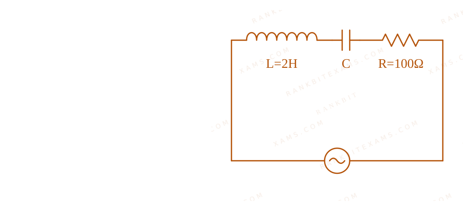
Using a variable-frequency a.c. voltage source, the maximum current measured in the given LCR circuit is 50 mA for V = 5 (100t)$V = 5\sin(100t)$. The values of L and R are shown in the figure. The capacitance of the capacitor (C) used is ____ $\mu\text{F}$.
A series LCR circuit with L=2H, R=100Ω and AC source V=5sin(100t).
Numerical Answer.Answer: 50 to 50
Solution
Related Formula
ω = 1√(LC)$$\omega = \frac{1}{\sqrt{LC}}$$
Core Logic
Current in an LCR circuit reaches a maximum value (measured as 50 mA$50 \text{ mA}$) exactly when the circuit is in resonance. At resonance, the inductive reactance equals the capacitive reactance, meaning XL = XC$X_L = X_C$, which gives the condition ω = 1/√(LC)$\omega = 1/\sqrt{LC}$.
Step 1: Identify Parameters
From the source equation V = 5 (100t)$V = 5\sin(100t)$:
ω = 100 rad/s$\omega = 100 \text{ rad/s}$
From the circuit diagram:
L = 2 H$L = 2 \text{ H}$
Sees: "maximum current" + "variable-frequency / given frequency" → Resonance! The impedance is purely resistive (Z=R$Z=R$), so ω L = 1/(ω C)$\omega L = 1/(\omega C)$. The 50 mA$50 \text{ mA}$ info is a distractor/cross-check (since Vpeak/R = 5/100 = 50 mA$V_{peak}/R = 5/100 = 50 \text{ mA}$, confirming resonance).
Chapter Mix
Class 12 Physics: Alternating Current
Q34jee_main_2026_24_january_morningPower in AC Circuit
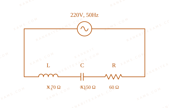
For the series LCR circuit connected with 220 V, 50 Hz a.c source as shown in the figure, the power factor is (α)/(10)$\frac{\alpha}{10}$. The value of α$\alpha$ is ____
A series LCR circuit connected to a 220 V, 50 Hz AC source.
To find the root mean square (rms) value of a varying current, we integrate the square of the current over the given time period, divide by the time period, and take the square root.
For any linearly varying quantity y = kt$y = kt$ passing through origin, the RMS value over time T$T$ is always Maximum Value√(3)$\frac{\text{Maximum Value}}{\sqrt{3}}$. A standard AC sine wave is 1/√(2)$1/\sqrt{2}$.
Chapter Mix
Class 12 Physics: Alternating Current
Q48jee_main_2026_28_january_eveningLR Circuit Power
An inductor stores 16 J$16 \text{ J}$ of magnetic field energy and dissipates 32 W$32 \text{ W}$ of thermal energy due to its resistance when an a.c. current of 2 A$2 \text{ A}$ (rms) and frequency 50 Hz$50 \text{ Hz}$ flows through it. The ratio of inductive reactance to its resistance is ____. ( π = 3.14$\pi = 3.14$ )
Numerical Answer.Answer: 314 to 314
Solution
Related Formula
UB = (1)/(2) L irms²$$U_B = \frac{1}{2} L i_{\text{rms}}^2$$P = irms² R$$P = i_{\text{rms}}^2 R$$XL = ω L = 2π f L$$X_L = \omega L = 2\pi f L$$
Core Logic
Solution for LR Circuit Power
The inductor acts as a series combination of an ideal inductor L$L$ and a resistor R$R$.
Given: Magnetic energy stored U = 16 J$U = 16 \text{ J}$, Power dissipated P = 32 W$P = 32 \text{ W}$, irms = 2 A$i_{\text{rms}} = 2 \text{ A}$, f = 50 Hz$f = 50 \text{ Hz}$.
Step 1: Calculate Inductance L
(1)/(2) L irms² = 16$$\frac{1}{2} L i_{\text{rms}}^2 = 16$$(1)/(2) L (2)² = 16$$\frac{1}{2} L (2)^2 = 16$$2L = 16 ⇒ L = 8 H$$2L = 16 \Rightarrow L = 8 \text{ H}$$
Step 2: Calculate Resistance R
irms² R = 32$$i_{\text{rms}}^2 R = 32$$
(2)² R = 32$(2)^2 R = 32$
4R = 32 ⇒ R = 8 Ω$$4R = 32 \Rightarrow R = 8 \, \Omega$$
The power dissipated inside a real inductor is exclusively due to its internal resistance (I²R$I^2R$). The magnetic energy stored relates exclusively to its inductance ((1)/(2)LI²$\frac{1}{2}LI^2$).
Chapter Mix
Class 12 Physics: Alternating Current
Q15jee_main_2025_03_april_eveningPower and RMS Peak Current Relationships
An electric bulb rated as 100W 220V is connected to an ac source of rms voltage 220 V. The peak value of current through the bulb is:
A. 0.64 A
B. 0.45 A
C. 2.2 A
D. 0.32 A
Solution
Related Formula
Power consumed in a purely resistive AC device (like a lightbulb) is:
P = Vrms Irms$$P = V_{\text{rms}} I_{\text{rms}}$$
The peak current I₀$I_0$ is related to the rms current Irms$I_{\text{rms}}$ by:
I₀ = √(2) Irms$$I_0 = \sqrt{2} I_{\text{rms}}$$
Core Logic
Given parameters:
Power P = 100~W$P = 100\mathrm{~W}$
rms Voltage Vrms = 220~V$V_{\text{rms}} = 220\mathrm{~V}$
Step 1: Calculate RMS Current (Irms$I_{\text{rms}}$)
Always remember that rated values specify the RMS limits. Since the source voltage matches the bulb's rated voltage exactly, the actual power equals the rated power (
$
Pattern Recognition
Always remember that rated values specify the RMS limits. Since the source voltage matches the bulb's rated voltage exactly, the actual power equals the rated power ($
100\mathrm{~W}). Do not confuse$). Do not confuse $I_{\text{rms}}($ ($0.45\mathrm{~A}) with the peak current$) with the peak current $I_0($ ($0.64\mathrm{~A}$).
Chapter Mix
Class 12 Physics: Alternating Current
More Alternating Current Questions — jee_main_2024_30_jan_morning
Practice past-year questions one chapter at a time. Pick an exam → subject → chapter and get every PYQ for that topic — pulled together from all past papers — with the chapter's key formulas alongside.