Given below are two statements : one is labelled as Assertion (A) and the other is labelled as Reason (R).
Assertion (A): Choke coil is simply a coil having a large inductance but a small resistance. Choke coils are used with fluorescent mercury-tube fittings. If household electric power is directly connected to a mercury tube, the tube will be damaged.
Reason (R): By using the choke coil, the voltage across the tube is reduced by a factor (R / R² + ω²L²)$\left(\mathrm{R} / \sqrt{\mathrm{R}^2 + \omega^2\mathrm{L}^2}\right)$ , where ω$\omega$ is frequency of the supply across resistor R and inductor L. If the choke coil were not used, the voltage across the resistor would be the same as the applied voltage.
In the light of the above statements, choose the most appropriate answer from the options given below:
A.Both (A) and (R) are true but (R) is not the correct explanation of (A).$\text{Both (A) and (R) are true but (R) is not the correct explanation of (A).}$
B.(A) is false but (R) is true.$\text{(A) is false but (R) is true.}$
C.Both (A) and (R) are true and (R) is the correct explanation of (A).$\text{Both (A) and (R) are true and (R) is the correct explanation of (A).}$
D.(A) is true but (R) is false.$\text{(A) is true but (R) is false.}$
A choke coil has a high inductance L$L$ and low resistance R$R$. It reduces the current through the mercury tube without wasting electrical power as heat. Statement (A) is correct. The average power dissipation is controlled by the low power factor φ$\cos \phi$. Reason (R) correctly explains that without a choke coil, the direct supply voltage could cause an overflow of current, destroying the tube filament.
Pattern Recognition
Choke coils use high L$L$ and low R$R$ to minimize power loss while reducing circuit current efficiently.
Chapter Mix
Class 12 Physics: Alternating Current
More Alternating Current Previous-Year Questions
Q48jee_main_2026_23_january_morningResonance
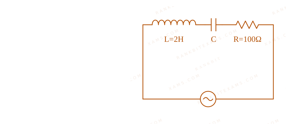
Using a variable-frequency a.c. voltage source, the maximum current measured in the given LCR circuit is 50 mA for V = 5 (100t)$V = 5\sin(100t)$. The values of L and R are shown in the figure. The capacitance of the capacitor (C) used is ____ $\mu\text{F}$.
A series LCR circuit with L=2H, R=100Ω and AC source V=5sin(100t).
Numerical Answer.Answer: 50 to 50
Solution
Related Formula
ω = 1√(LC)$$\omega = \frac{1}{\sqrt{LC}}$$
Core Logic
Current in an LCR circuit reaches a maximum value (measured as 50 mA$50 \text{ mA}$) exactly when the circuit is in resonance. At resonance, the inductive reactance equals the capacitive reactance, meaning XL = XC$X_L = X_C$, which gives the condition ω = 1/√(LC)$\omega = 1/\sqrt{LC}$.
Step 1: Identify Parameters
From the source equation V = 5 (100t)$V = 5\sin(100t)$:
ω = 100 rad/s$\omega = 100 \text{ rad/s}$
From the circuit diagram:
L = 2 H$L = 2 \text{ H}$
Sees: "maximum current" + "variable-frequency / given frequency" → Resonance! The impedance is purely resistive (Z=R$Z=R$), so ω L = 1/(ω C)$\omega L = 1/(\omega C)$. The 50 mA$50 \text{ mA}$ info is a distractor/cross-check (since Vpeak/R = 5/100 = 50 mA$V_{peak}/R = 5/100 = 50 \text{ mA}$, confirming resonance).
Chapter Mix
Class 12 Physics: Alternating Current
Q34jee_main_2026_24_january_morningPower in AC Circuit
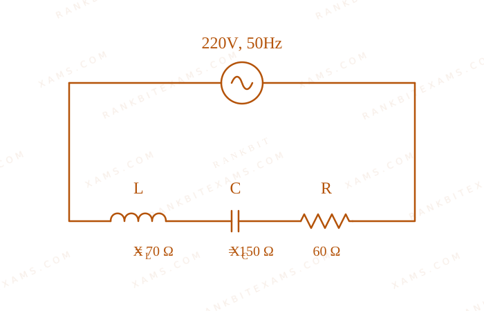
For the series LCR circuit connected with 220 V, 50 Hz a.c source as shown in the figure, the power factor is (α)/(10)$\frac{\alpha}{10}$. The value of α$\alpha$ is ____
A series LCR circuit connected to a 220 V, 50 Hz AC source.
To find the root mean square (rms) value of a varying current, we integrate the square of the current over the given time period, divide by the time period, and take the square root.
For any linearly varying quantity y = kt$y = kt$ passing through origin, the RMS value over time T$T$ is always Maximum Value√(3)$\frac{\text{Maximum Value}}{\sqrt{3}}$. A standard AC sine wave is 1/√(2)$1/\sqrt{2}$.
Chapter Mix
Class 12 Physics: Alternating Current
Q48jee_main_2026_28_january_eveningLR Circuit Power
An inductor stores 16 J$16 \text{ J}$ of magnetic field energy and dissipates 32 W$32 \text{ W}$ of thermal energy due to its resistance when an a.c. current of 2 A$2 \text{ A}$ (rms) and frequency 50 Hz$50 \text{ Hz}$ flows through it. The ratio of inductive reactance to its resistance is ____. ( π = 3.14$\pi = 3.14$ )
Numerical Answer.Answer: 314 to 314
Solution
Related Formula
UB = (1)/(2) L irms²$$U_B = \frac{1}{2} L i_{\text{rms}}^2$$P = irms² R$$P = i_{\text{rms}}^2 R$$XL = ω L = 2π f L$$X_L = \omega L = 2\pi f L$$
Core Logic
Solution for LR Circuit Power
The inductor acts as a series combination of an ideal inductor L$L$ and a resistor R$R$.
Given: Magnetic energy stored U = 16 J$U = 16 \text{ J}$, Power dissipated P = 32 W$P = 32 \text{ W}$, irms = 2 A$i_{\text{rms}} = 2 \text{ A}$, f = 50 Hz$f = 50 \text{ Hz}$.
Step 1: Calculate Inductance L
(1)/(2) L irms² = 16$$\frac{1}{2} L i_{\text{rms}}^2 = 16$$(1)/(2) L (2)² = 16$$\frac{1}{2} L (2)^2 = 16$$2L = 16 ⇒ L = 8 H$$2L = 16 \Rightarrow L = 8 \text{ H}$$
Step 2: Calculate Resistance R
irms² R = 32$$i_{\text{rms}}^2 R = 32$$
(2)² R = 32$(2)^2 R = 32$
4R = 32 ⇒ R = 8 Ω$$4R = 32 \Rightarrow R = 8 \, \Omega$$
The power dissipated inside a real inductor is exclusively due to its internal resistance (I²R$I^2R$). The magnetic energy stored relates exclusively to its inductance ((1)/(2)LI²$\frac{1}{2}LI^2$).
Chapter Mix
Class 12 Physics: Alternating Current
Q15jee_main_2025_03_april_eveningPower and RMS Peak Current Relationships
An electric bulb rated as 100W 220V is connected to an ac source of rms voltage 220 V. The peak value of current through the bulb is:
A. 0.64 A
B. 0.45 A
C. 2.2 A
D. 0.32 A
Solution
Related Formula
Power consumed in a purely resistive AC device (like a lightbulb) is:
P = Vrms Irms$$P = V_{\text{rms}} I_{\text{rms}}$$
The peak current I₀$I_0$ is related to the rms current Irms$I_{\text{rms}}$ by:
I₀ = √(2) Irms$$I_0 = \sqrt{2} I_{\text{rms}}$$
Core Logic
Given parameters:
Power P = 100~W$P = 100\mathrm{~W}$
rms Voltage Vrms = 220~V$V_{\text{rms}} = 220\mathrm{~V}$
Step 1: Calculate RMS Current (Irms$I_{\text{rms}}$)
Always remember that rated values specify the RMS limits. Since the source voltage matches the bulb's rated voltage exactly, the actual power equals the rated power (
$
Pattern Recognition
Always remember that rated values specify the RMS limits. Since the source voltage matches the bulb's rated voltage exactly, the actual power equals the rated power ($
100\mathrm{~W}). Do not confuse$). Do not confuse $I_{\text{rms}}($ ($0.45\mathrm{~A}) with the peak current$) with the peak current $I_0($ ($0.64\mathrm{~A}$).
Chapter Mix
Class 12 Physics: Alternating Current
More Alternating Current Questions — jee_main_2025_29_jan_morning
Practice past-year questions one chapter at a time. Pick an exam → subject → chapter and get every PYQ for that topic — pulled together from all past papers — with the chapter's key formulas alongside.