JEE Main · Physics → Steady

Current Electricity appeared 50 times across 3 years — 5.8% of Physics. This question is from Combination of Resistors.

Year 2026 2025 2024 Total
Questions 18 13 19 50

A wire of resistance R is bent into an equilateral triangle and an identical wire is bent into a square. The ratio of resistance between the two end points of an edge of the triangle to that of the square is

Solution & Explanation

Related Formula
R = ρ A R ∝
Core Logic

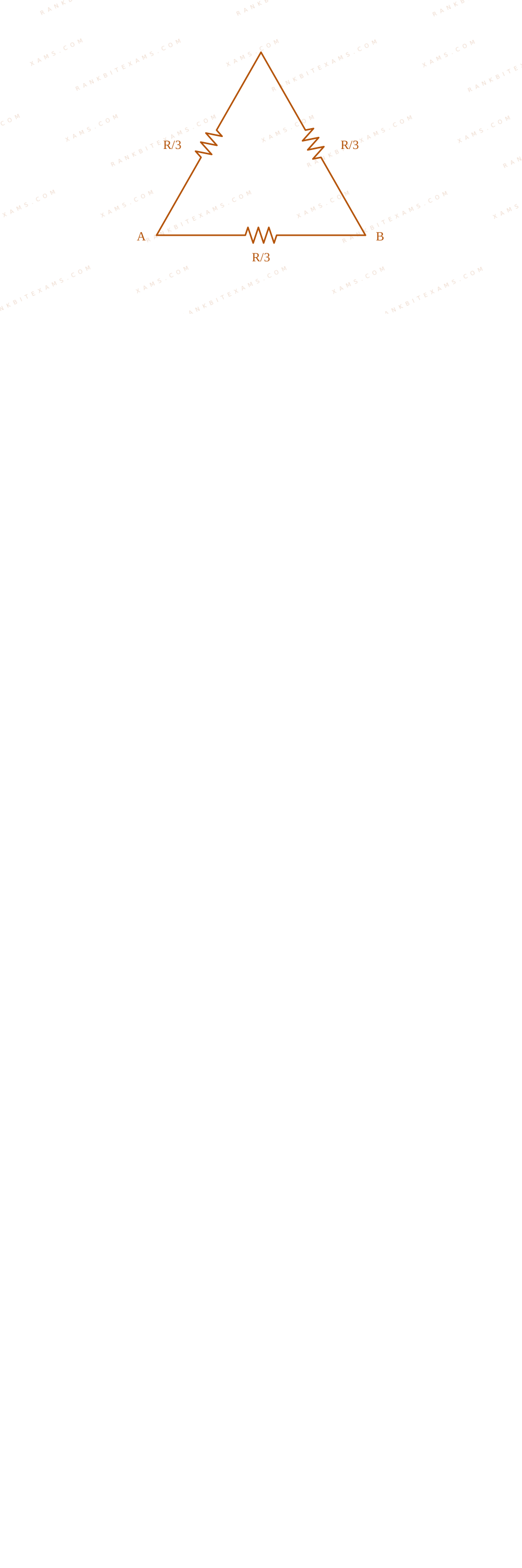
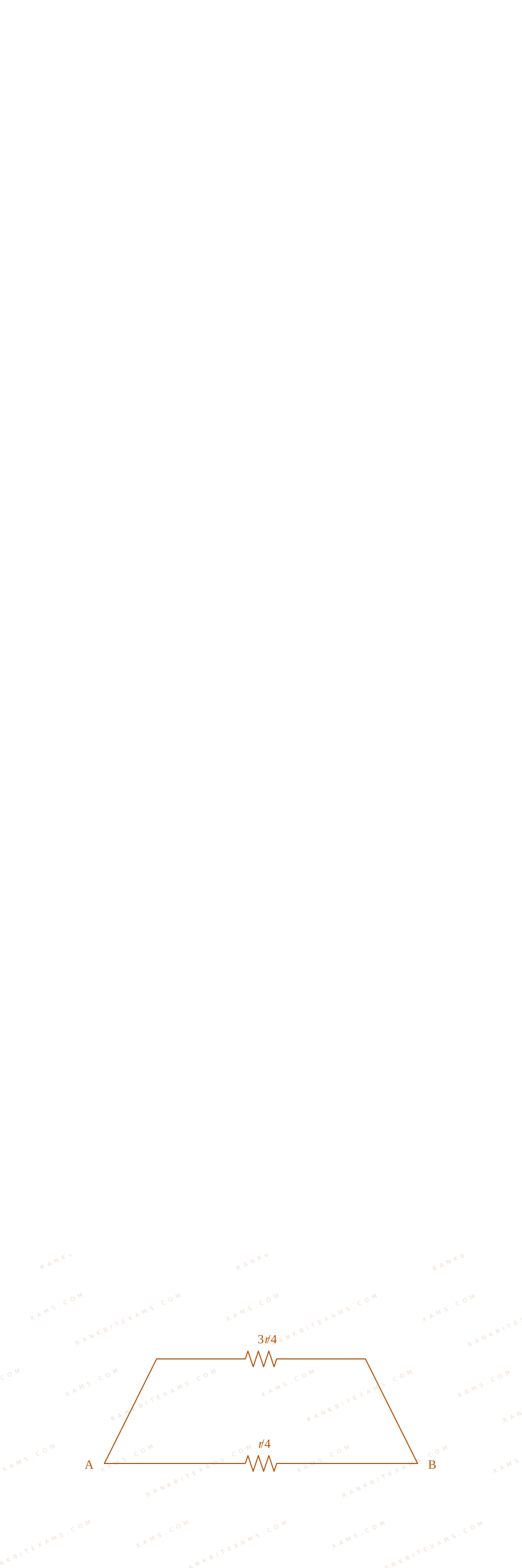
For the equilateral triangle, the total resistance R is divided into three equal line parts of value R3 each:

Visual representation of triangle and square edge divisions for Q15

Visual representation of triangle and square edge divisions for Q15

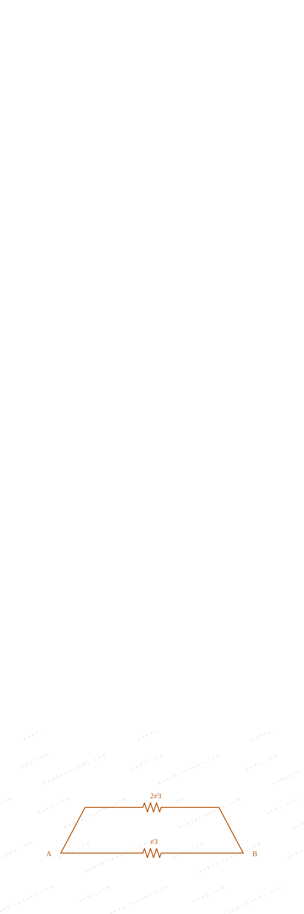
An edge configuration places one part in parallel with the other two series steps:

(Req)₁ = ( 2R3) · ( R3) 2R3 + R3 = (2)/(9)R

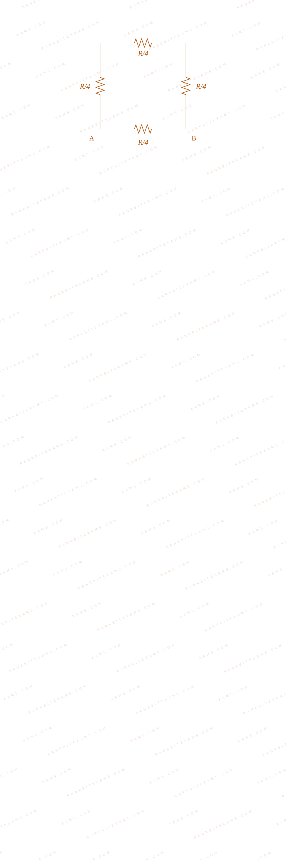
For the square, the wire resistance R divides into four parts of R4 each:

Visual representation of triangle and square edge divisions for Q15

Visual representation of triangle and square edge divisions for Q15

An edge calculation pairs one section in parallel with the remaining three loops in series:

(Req)₂ = ( 3R4) · ( R4) 3R4 + R4 = (3)/(16)R

Taking the ratio between these geometric layouts:

Step 1: Final Ratio Calculation
(Req)₁(Req)₂ = (2)/(9)R(3)/(16)R = (32)/(27)

This selects option (4).

Pattern Recognition

For a regular polygon with N identical sides formed from a wire of resistance R, the resistance across one edge is always given by (N-1)N²R.

Chapter Mix

Class 12 Physics: Current Electricity

Reference Study Guides

More Current Electricity Previous-Year Questions — Page 9

Q jee_main_2024_30_january_evening Voltmeter Resistance
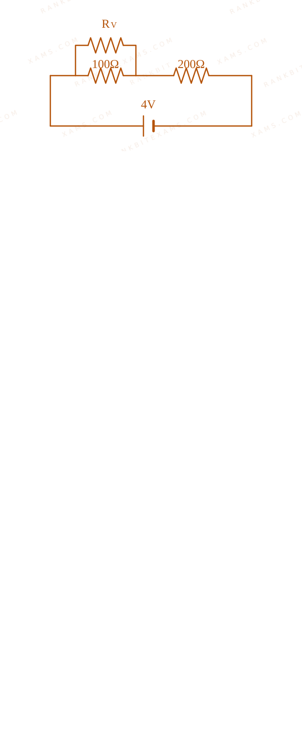
Two resistance of 100Ω and 200Ω are connected in series with a battery of 4 ~V and negligible internal resistance. A voltmeter is used to measure voltage across 100Ω resistance, which gives reading as 1 ~V. The resistance of voltmeter must be ________ Ω.
Numerical Answer. Answer: 200 to 200

Solution

Related Formula
V = I Req Rparallel = (R₁ R₂)/(R₁ + R₂)
Core Logic

Voltmeter Resistance diagram for Q60 - JEE Main 2024 Evening

The voltmeter has some internal resistance Rv and is connected in parallel with the 100Ω resistor. The equivalent resistance of this parallel combination is Rₚ = (100 Rv)/(100 + Rv). This combination is in series with the 200Ω resistor. The total voltage applied is 4 ~V.

Step 1: Set up Voltage Divider

The voltage across the parallel combination (the voltmeter reading) is 1 ~V. Therefore, the voltage across the 200Ω resistor must be 4 ~V - 1 ~V = 3 ~V. Using the voltage divider rule (or equating currents since they are in series):

I = V₂₀₀200 = (3)/(200) ~A
Step 2: Solve for Voltmeter Resistance

The current I also flows through the parallel combination Rₚ: Vₚ = I Rₚ

1 = ((3)/(200)) ( (100 Rv)/(100 + Rv) ) 200 (100 + Rv) = 300 Rv 20000 + 200 Rv = 300 Rv

100 Rv = 20000

Rv = 200 Ω
Pattern Recognition

If the voltage splits as 1V to 3V, the resistances must be in a 1:3 ratio. So Rₚ = 200 / 3. Equating 100 Rv / (100+Rv) = 200/3 instantly gives Rv = 200.

Chapter Mix

Class 12 Physics: Current Electricity
Q48 jee_main_2024_30_january_evening Power Dissipation in Resistors
When a potential difference V is applied across a wire of resistance R, it dissipates energy at a rate W. If the wire is cut into two halves and these halves are connected mutually parallel across the same supply, the energy dissipation rate will become:
  • A. 1 / 4 W
  • B. 1 / 2 W
  • C. 2 ~W
  • D. 4 ~W

Solution

Related Formula
P = V²Req
Core Logic

Initially, the power (rate of energy dissipation) is W = (V²)/(R). When the wire is cut into two halves, each half will have a resistance of (R)/(2) (since resistance is directly proportional to length).

Step 1: Equivalent Resistance

When these two halves (each of (R)/(2)) are connected in parallel, their equivalent resistance Req is:

Req = (((R)/(2)) × ((R)/(2)))/((R)/(2) + (R)/(2)) = (R)/(4)
Step 2: New Power Dissipation

The new rate of energy dissipation W' across the same potential difference V is:

W' = V²Req = (V²)/((R)/(4)) = 4 (V²)/(R)

W' = 4W

Pattern Recognition

Cutting a resistor into n equal parts and connecting them in parallel reduces the total resistance by a factor of n². Consequently, for a constant voltage supply, the power dissipated increases by a factor of n².

Chapter Mix

Class 12 Physics: Current Electricity
Q jee_main_2024_30_jan_morning Cells in Opposition and Terminal Voltage
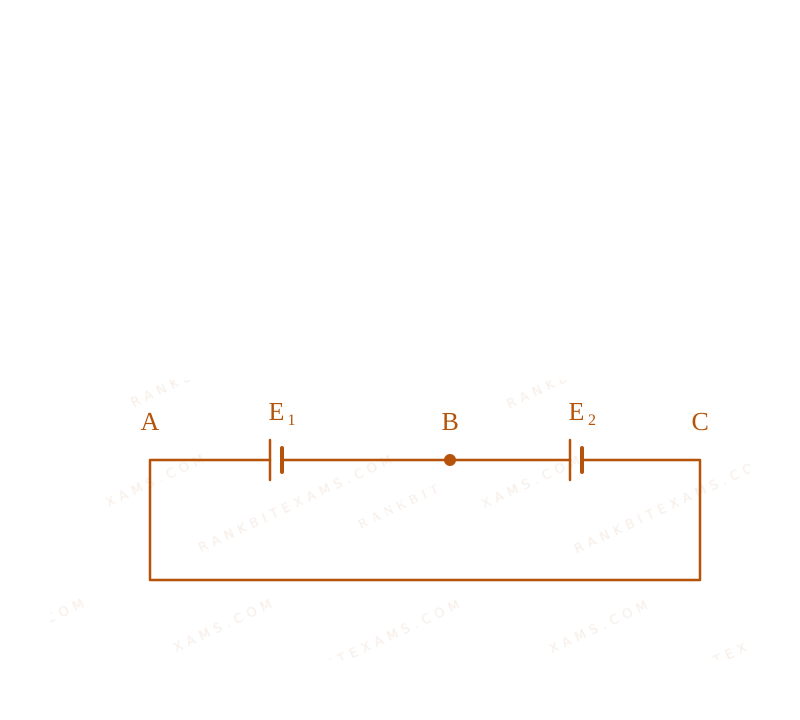
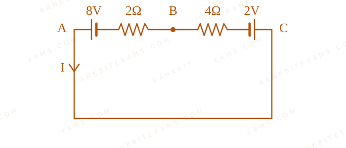
Two cells are connected in opposition as shown. Cell E₁ is of 8V emf and 2Ω internal resistance; the cell E₂ is of 2V emf and 4Ω internal resistance. The terminal potential difference of cell E₂ is:
Cells in Opposition and Terminal Voltage diagram for Q52 - JEE Main 2024 Morning
Two batteries pushing current against each other.
Numerical Answer. Answer: 6 to 6

Solution

Related Formula
I = EₙₑₜReq V = E - Ir (Discharging) V = E + Ir (Charging)
Core Logic

Circuit with marked nodes for Kirchhoff analysis.
Two batteries pushing current against each other.
Because the cells are in opposition, the net EMF drives current from the higher potential cell (8V) to the lower potential cell (2V). Thus, the 2V cell acts as a load and undergoes charging.

Step 1: Calculate Total Current
I = (8 - 2)/(2 + 4) = (6)/(6) = 1 ~A
Step 2: Terminal Potential of Cell 2

Since cell E₂ is being charged, its terminal potential difference is:

V₂ = E₂ + I r₂

Applying Kirchhoff's rule across cell E₂ (from node C to B):

VC - VB = E₂ + I r₂ = 2 + (1)(4) = 6 ~V
Pattern Recognition

When a smaller battery is forced backwards by a larger battery, it gets "charged". Consequently, its terminal voltage increases above its nominal EMF: V = E + Ir.

Chapter Mix

Class 12 Physics: Current Electricity
Q33 jee_main_2024_30_jan_morning Resistors in Series and Voltage Dividers
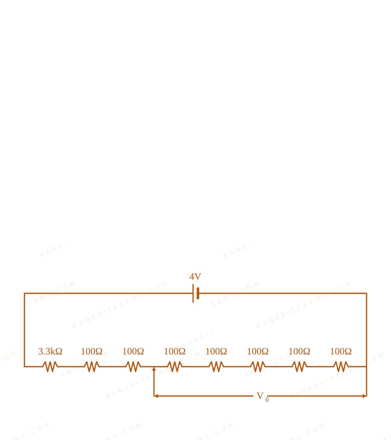
A potential divider circuit is shown in figure. The output voltage V₀ is
Resistors in Series and Voltage Dividers diagram for Q33 - JEE Main 2024 Morning
Circuit containing multiple resistors in series and parallel calculating a specific output voltage.
  • A. 4 ~V
  • B. 2 ~mV
  • C. 0.5 ~V
  • D. 12 ~mV

Solution

Related Formula

V = IR

Req = R₁ + R₂ + + Rₙ (for series)
Core Logic

Observe the circuit diagram. The total equivalent resistance Req of the series network must be calculated by summing all the resistance values shown in the main branch.

Step 1: Calculate Total Resistance and Current

From the given network, assuming the total series resistance is 4000 Ω (comprising the 3.3kΩ resistor and seven 100 Ω resistors).

Req = 4000 Ω

The total voltage applied across the network is 4 ~V.

i = VReq = (4)/(4000) = (1)/(1000) ~A
Step 2: Calculate Output Voltage

The output voltage V₀ is tapped across five 100 Ω resistors.

Rout = 5 × 100 Ω = 500 Ω

Thus, the output voltage is:

V₀ = i · Rout = ((1)/(1000)) × 500 = 0.5 ~V
Pattern Recognition

A potential divider simply scales the input voltage by the fraction of the resistance tapped over the total resistance: V₀ = Vᵢₙ × (Rₜₐₚ / Rtotal). Standard DC circuit division.

Chapter Mix

Class 12 Physics: Current Electricity

Q43 jee_main_2024_30_jan_morning Temperature Dependence of Resistivity
An electric toaster has resistance of 60Ω at room temperature (27°C). The toaster is connected to a 220V supply. If the current flowing through it reaches 2.75A, the temperature attained by toaster is around: (if α = 2× 10⁻⁴ / °C)
  • A. 694° C
  • B. 1235°C
  • C. 1694°C
  • D. 1667°C

Solution

Related Formula
R = (V)/(I) R = R₀ (1 + α Δ T)
Core Logic

First, evaluate the final resistance RT at the operating condition using Ohm's law. Second, plug the final resistance into the linear temperature dependence equation for resistance to solve for final temperature T.

Step 1: Calculate Final Resistance

Given V = 220 ~V and I = 2.75 ~A:

RT = (220)/(2.75) = 80 Ω
Step 2: Apply Temperature Equation

We know R₂₇ = 60 Ω.

RT = R₂₇ [1 + α (T - 27)] 80 = 60 [1 + 2 × 10⁻⁴ (T - 27)] (80)/(60) = 1 + 2 × 10⁻⁴ (T - 27) (4)/(3) - 1 = 2 × 10⁻⁴ (T - 27) (1)/(3) = 2 × 10⁻⁴ (T - 27)
Step 3: Solve for T
T - 27 = 16 × 10⁻⁴ T - 27 = (10000)/(6) = 1666.67 T = 1666.67 + 27 ≈ 1693.67 ⇒ 1694^° C
Pattern Recognition

Always separate the final temperature T from Δ T. The most common error is forgetting to add back the initial reference temperature (27^) at the end.

Chapter Mix

Class 12 Physics: Current Electricity

More Current Electricity Questions — jee_main_2025_28_jan_morning

Practice all Current Electricity previous-year questions →

Rankbit System
JEE Physics: Waves (+15.5%) | Electrostatics: Concentric Shells (-29.7%) | Modern Physics: Photoelectric Clones (+34.2%) | Mathematics: Definite Integrals (+18.1%) | Chemistry: Coordination Splitting (-11.4%) | JEE Physics: Waves (+15.5%) | Electrostatics: Concentric Shells (-29.7%) | Modern Physics: Photoelectric Clones (+34.2%) | Mathematics: Definite Integrals (+18.1%) | Chemistry: Coordination Splitting (-11.4%)