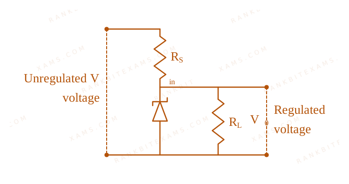
The following diagram shows a Zener diode as a voltage regulator. The Zener diode is rated at VZ = 5V and the desired current in load is 5 mA. The unregulated voltage source can supply up to 25V. Considering the Zener diode can withstand four times of the load current, the value of resistor RS (shown in circuit) should be ____ Ω.
Zener Diode diagram for Q37 - JEE Main 2026 Morning
Circuit containing unregulated voltage, series resistor Rs, Zener diode, and load resistor.

Solution & Explanation

Related Formula
Itotal = IZ + IL Vᵢₙ - VZ = Itotal RS
Core Logic

The question is dropped by the examination authority, meaning there was an anomaly in data or multiple correct interpretations, likely due to imprecise wording regarding the maximum source voltage and the exact safe current rating. In a nominal calculation, I_Zmax = 4 × 5 mA = 20 mA. Total current I = 25 mA. RS = (25 - 5) / (25 × 10⁻³) = 800Ω, which is not in the options.

Step 1: Final Conclusion

Question Dropped.

Pattern Recognition

Sees: "Question Dropped" → This often occurs when mathematical data maps to none of the provided MCQs.

Chapter Mix

Class 12 Physics: Semiconductor Electronics: Materials, Devices and Simple Circuits

Reference Study Guides

More Semiconductor Electronics: Materials, Devices and Simple Circuits Previous-Year Questions — Page 2

Q48 jee_main_2026_24_january_morning Zener Diode
A voltage regulating circuit consisting of Zener diode, having break-down voltage of 10 V and maximum power dissipation of 0.4 W, is operated at 15 V. The approximate value of protective resistance in this circuit is ____ Ω.
Numerical Answer. Answer: 125 to 125

Solution

Related Formula

PZ = VZ IZ

Vᵢₙ = IZ RS + VZ
Core Logic

For the Zener diode, the maximum power dissipated is:

PD = 0.4 W

Since PD = VZ IZ:

0.4 = 10 × IZ IZ = 0.04 A
Step 1: Find Protective Series Resistance
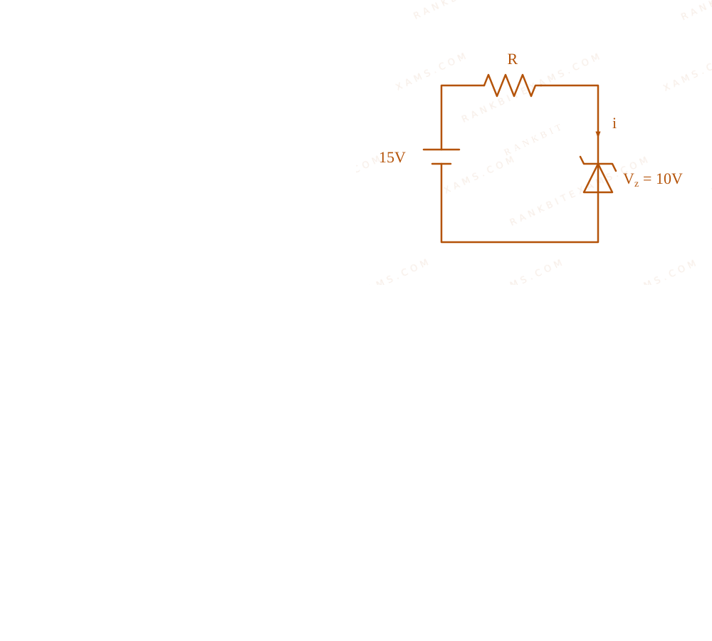
Zener diode voltage regulator circuit

The voltage drop across the series protective resistance R is:

VR = Vᵢₙ - VZ = 15 - 10 = 5 V

Using Ohm's law, R = (VR)/(IZ):

R = (5)/(0.04) = (500)/(4) = 125 Ω
Pattern Recognition

To secure a Zener against burning out, calculate its max safe current via Pmax / Vz. Feed this current into the required voltage drop (Vᵢₙ - Vz) to get the exact protective resistance.

Chapter Mix

Class 12 Physics: Semiconductor Electronics
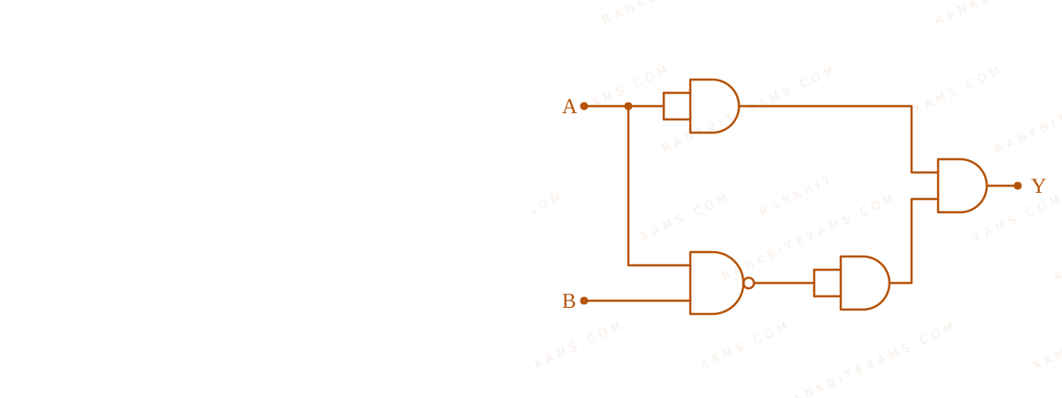
Q39 jee_main_2026_24_january_evening Logic Gates
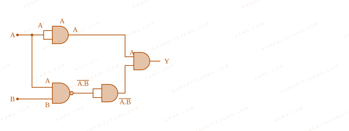
Identify the correct truth table of the given logical circuit.
Logic Gates diagram for Q39 - JEE Main 2026 Evening
A combination of logic gates resulting in output Y.
  • A.
    ABY
    000
    011
    101
    110
  • B.
    ABY
    001
    010
    101
    110
  • C.
    ABY
    000
    010
    101
    110
  • D.
    ABY
    001
    010
    101
    110

Solution

Related Formula
De Morgan's Laws: A · B = A + B
Core Logic

Logic Gates diagram for Q39 - JEE Main 2026 Evening
A combination of logic gates resulting in output Y.

Let's trace the logic line by line. Top branch: A passes through an AND gate with both inputs tied to A, so it remains A. Bottom branch: A and B pass through a NAND gate, yielding A · B. Then it passes through an AND gate with inputs tied together, so it remains A · B.

Step 1: Boolean Expression

Finally, the inputs A and A · B are fed into a final AND gate.

Y = A · A · B

Applying De Morgan's Law:

Y = A · ( A + B) Y = A · A + A · B
Step 2: Simplify

Since A · A = 0, we have:

Y = 0 + A B = A B

Checking values: If A=1, B=0, then Y = 1 · 1 = 1. For all other combinations, Y = 0.

Logic Gates diagram for Q39 - JEE Main 2026 Evening
A combination of logic gates resulting in output Y.

Pattern Recognition

An AND gate acting on A and NAND(A, B) inherently acts as a "strictly A and NOT B" checker. The boolean algebra instantly simplifies A( AB) to A B.

Chapter Mix

Class 12 Physics: Semiconductor Electronics
Q35 jee_main_2026_28_january_morning Semiconductor Diode
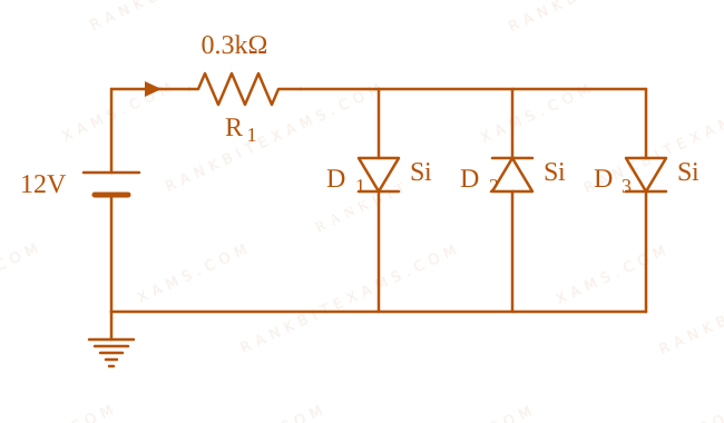
Assuming in forward bias condition there is a voltage drop of 0.7 V across a silicon diode, the current through diode D₁ in the circuit is ____ mA. (Assume all diodes in the given circuit are identical)
Circuit with diodes for Q35
Circuit containing a 12V source, a 0.3kOhm resistor, and three diodes D1, D2, D3 in parallel.
  • A. 20.15
  • B. 11.7
  • C. 17.6
  • D. 18.8

Solution

Related Formula
I = (V - Vd)/(R)
Core Logic

Check the polarity of the battery to determine which diodes are forward-biased. Diodes D₁ and D₂ are forward-biased, while D₃ is reverse-biased (acts as an open circuit). Because D₁ and D₂ are in parallel, the total voltage drop across the parallel combination is just 0.7 ~V.

Step 1: Loop Equation

Applying KVL to the main loop containing the forward-biased diodes:

12 - 0.3 × 10³ Itotal - 0.7 = 0 11.3 = 300 · Itotal
Step 2: Total Current
Itotal = (11.3)/(300) ~A = 37.66 × 10⁻³ ~A = 37.66 ~mA
Step 3: Current Division

Since D₁ and D₂ are identical and in parallel, the total current divides equally between them.

ID1 = Itotal2 = (37.66)/(2) ~mA = 18.83 ~mA

Rounding to nearest option gives 18.8 ~mA.

Pattern Recognition

Identical diodes in parallel share the current equally. The voltage drop across the entire parallel diode bank is just the drop of one diode (0.7 ~V).

Chapter Mix

Class 12 Physics: Semiconductor Electronics: Materials, Devices and Simple Circuits

Q30 jee_main_2026_28_january_evening Logic Gates
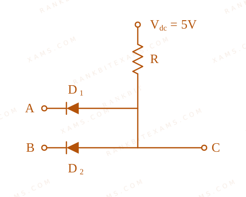
Two p-n junction diodes D₁ and D₂ are connected as shown in figure.
Logic Gates diagram for Q30 - JEE Main 2026 Evening
A logic gate formed using two diodes connected to a 5V supply through a pull-up resistor.
A and B are input signals and C is the output. The given circuit will function as a ____.
  • A. OR Gate
  • B. NOR Gate
  • C. NAND Gate
  • D. AND Gate

Solution

Core Logic

The circuit contains two diodes with their n-sides connected to the inputs A and B, and their p-sides tied together and connected to +5V through a resistor R. The output C is taken from the common p-side junction.

Step 1: Analyzing the Truth Table

If either A = 0 (ground) or B = 0 (ground), the corresponding diode becomes forward biased. Current flows through the resistor R, dropping the voltage at C to near 0V (Logic 0). If both A = 1 (+5V) and B = 1 (+5V), both diodes are reverse biased. No current flows through R, so the voltage at C remains at +5V (Logic 1).

Step 2: Conclusion

The output C is 1 ONLY when both inputs A AND B are 1. This corresponds exactly to the truth table of an AND Gate.

Pattern Recognition

Diodes pointing away from the inputs with a pull-up resistor (connected to +Vcc) form an AND gate. If diodes point towards the inputs with a pull-down resistor to ground, it's an OR gate.

Chapter Mix

Class 12 Physics: Semiconductor Electronics: Materials, Devices and Simple Circuits

Q13 jee_main_2025_02_april_evening Logic Gates
In the digital circuit shown in the figure, for the given inputs the P and Q values are :
Digital logic gate circuit diagram with inputs 1 and 1
The circuit has two inputs equal to 1, passing through multiple gates to produce outputs P and Q.
  • A. P = 1, Q = 1
  • B. P = 0, Q = 0
  • C. P = 0, Q = 1
  • D. P = 1, Q = 0

Solution

Related Formula

Truth relations of basic logic operations:

  • NAND operation: Y = A · B
  • NOR operation: Y = A + B
  • NOT operation: Y = A
  • OR operation: Y = A + B
Core Logic

The inputs are:

  • Top input = 1
  • Bottom input = 1
  • Let's analyze step-by-step from left to right:

  • First Gate (NAND gate at the top-left):
  • Inputs are 1 and 1.
  • Output = 1 · 1 = 0.
  • Bottom-left path with NOT gates:
  • Top input (1) goes to a NOT gate, producing 0.
  • Bottom input (1) goes to a NOT gate, producing 0.
  • These two 0 values feed into the OR gate:
  • Output = 0 + 0 = 0.
Step 1: Calculate output P

Now trace the path to P:

  • The inputs to the top-right AND gate are:
  • Output of the top-left NAND gate = 0
  • Output of the bottom-left OR gate = 0
  • Therefore, output P is:
P = 0 · 0 = 0
Step 2: Calculate output Q

Now trace the path to Q:

  • The gate at the bottom-right is a NOR gate with two inputs:
  • Input 1: Output of the top-left NAND gate (0) inverted by a NOT gate = 0 = 1.
  • Input 2: Output of the bottom-left OR gate (0).
  • Passing these inputs (1 and 0) through the final NOR gate:
Q = 1 + 0 = 1 = 0

Thus, both P = 0 and Q = 0.

Pattern Recognition

Sees: Combinational trace with inverted nodes. Trap: Missing bubbles (NOT gates) representing inversion on internal circuit paths. Shortcut: The first NAND gate output is 0 (since both inputs are 1). This 0 directly goes to the upper AND gate, immediately guaranteeing output P = 0 (eliminates options 1 and 4). Now, you only need to evaluate Q to choose between options 2 and 3.

Chapter Mix

Class 12 Physics: Semiconductor Electronics: Materials, Devices and Simple Circuits

More Semiconductor Electronics: Materials, Devices and Simple Circuits Questions — jee_main_2026_23_january_morning

Practice all Semiconductor Electronics: Materials, Devices and Simple Circuits previous-year questions →

Rankbit System
JEE Physics: Waves (+15.5%) | Electrostatics: Concentric Shells (-29.7%) | Modern Physics: Photoelectric Clones (+34.2%) | Mathematics: Definite Integrals (+18.1%) | Chemistry: Coordination Splitting (-11.4%) | JEE Physics: Waves (+15.5%) | Electrostatics: Concentric Shells (-29.7%) | Modern Physics: Photoelectric Clones (+34.2%) | Mathematics: Definite Integrals (+18.1%) | Chemistry: Coordination Splitting (-11.4%)