Consider the following statements:
A. The junction area of solar cell is made very narrow compared to a photo diode.
B. Solar cells are not connected with any external bias.
C. LED is made of lightly doped p-n junction.
D. Increase of forward current results in continuous increase of LED light intensity.
E. LEDs have to be connected in forward bias for emission of light.
Choose the correct answer from the options given below :
A.B, D, E Only
B.A, C Only
C.A, C, E Only
D.B, E Only
Solution & Explanation
Core Logic
Let's analyze each statement conceptually:
Statement A: Solar cells require a wide surface layer area to intercept maximum sunlight illumination, so junction area is large.
Statement B: True. Solar cells operate spontaneously to provide power to loads without requiring external bias voltage.
Statement C: False. LEDs are made of heavily doped junctions to maximize recombination probability.
Statement D: False. Beyond a critical limit, high currents cause heating that drops efficiency, so emission intensity does not increase infinitely.
Statement E: True. Forward biasing allows minority injection leading to radiative recombination.
Step 1: Selecting Option
Since statements B and E are purely accurate, the correct grouping option is B, E Only.
Pattern Recognition
Remember: LEDs = Forward Bias, Photodiodes = Reverse Bias, Solar Cells = Zero External Bias.
Chapter Mix
Class 12 Physics: Semiconductor Electronics: Materials, Devices and Simple Circuits
NOR Gate: A+B, NAND Gate: A · B$$\text{NOR Gate: } \overline{A+B}, \quad \text{NAND Gate: } \overline{A \cdot B}$$
Core Logic
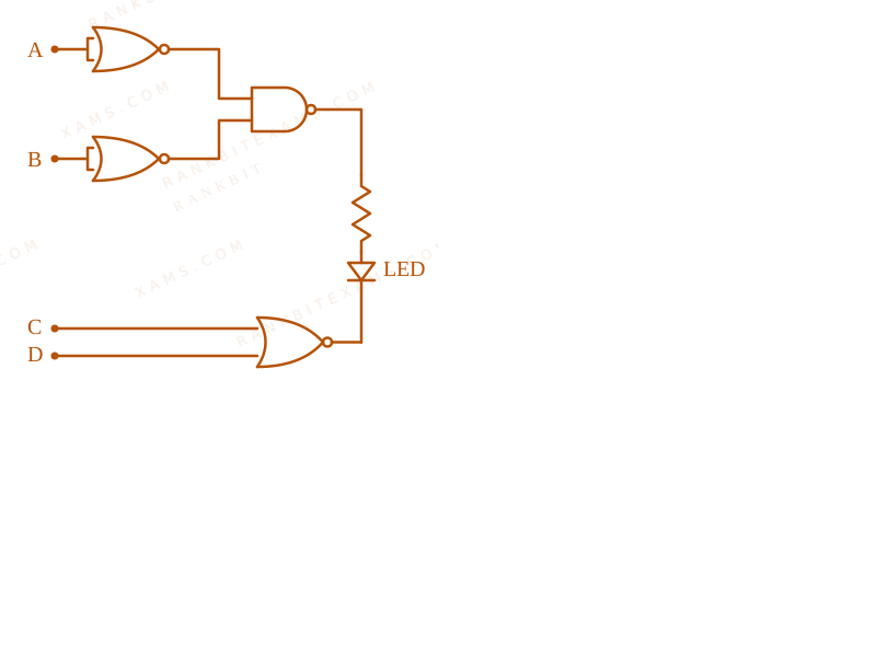
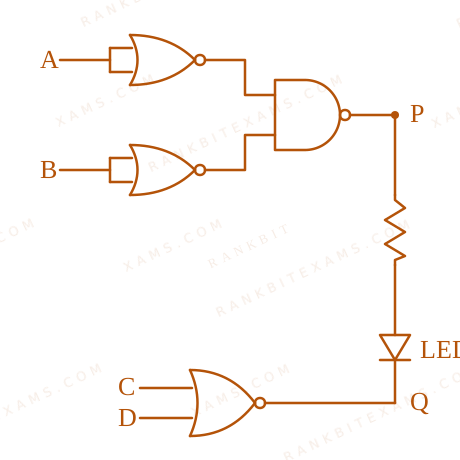
Logic gate circuit diagram connected to an LED.
LED will glow in forward biasing when point P is at higher potential (1) and point Q is at lower potential (0).
Testing option (4) [1101]:
Inputs A=1, B=1 through NOR and NAND gates yield P = 1.
Inputs C=1, D=0 through NOR gate yields Q = 0.
Forward bias established, LED glows.
Pattern Recognition
Sees: Logic gates combination with LED forward biasing condition.
Shortcut: Check forward bias requirement (P=1, Q=0) for each option combination.
Check: Option (4) satisfies the condition. ✓
Chapter Mix
Class 12 Physics: Semiconductor Electronics
Q35jee_main_2026_22_january_eveningLogic Gates and Truth Tables
The correct truth table for the given input data of the following logic gate is :
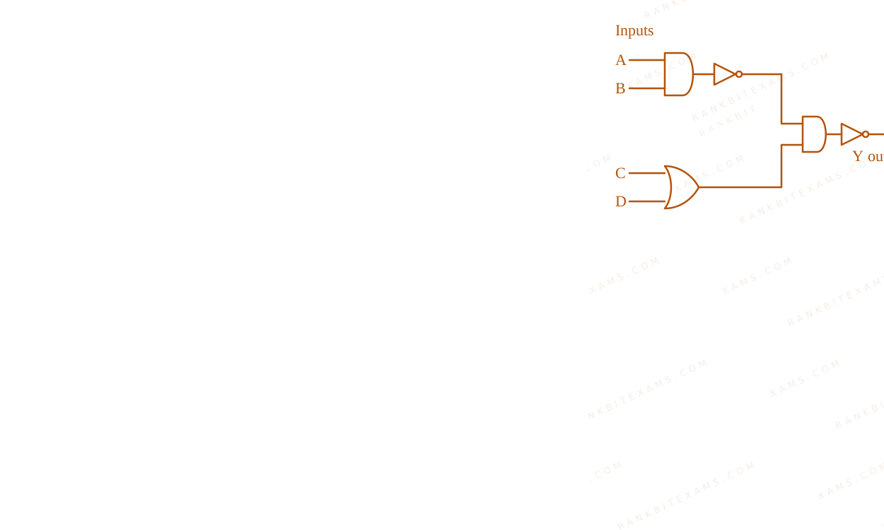
The figure illustrates a combined logic circuit with inputs A, B, C, D feeding into AND, OR, and NOT gates to produce output Y.
A.
Inputs
Output
A
B
C
D
Y
1
1
0
1
1
0
0
1
1
0
1
0
1
0
1
1
1
1
1
0
B.
Inputs
Output
A
B
C
D
Y
1
1
0
1
1
0
0
1
1
0
1
0
1
0
0
1
1
1
1
1
C.
Inputs
Output
A
B
C
D
Y
1
1
0
1
0
0
0
1
1
0
1
0
1
0
1
1
1
1
1
1
D.
Inputs
Output
A
B
C
D
Y
1
1
0
1
0
0
0
1
1
1
1
0
1
0
1
1
1
1
1
1
Solution
Related Formula
Y = ( A · B) · (C + D)$$Y = \overline{(\overline{A \cdot B}) \cdot (C + D)}$$
Applying De Morgan's Law:
Y = (A · B) + ( C + D)$$Y = (A \cdot B) + (\overline{C + D})$$
Core Logic
Analyzing the expression step by step:
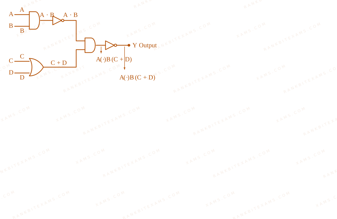
Upper branch: A$A$ and B$B$ pass through NAND gate arrow A · B$\rightarrow \overline{A \cdot B}$.
Lower branch: C$C$ and D$D$ pass through OR gate arrow (C + D)$\rightarrow (C + D)$.
Combined in AND gate followed by NOT gate (NAND equivalent output stage):
Y = ( A · B) · (C + D) = (A · B) + ( C + D)$$Y = \overline{(\overline{A \cdot B}) \cdot (C + D)} = (A \cdot B) + (\overline{C + D})$$
The figure illustrates a combined logic circuit with inputs A, B, C, D feeding into AND, OR, and NOT gates to produce output Y.
Step 1: Final Conclusion
Option (2) presents the correct truth table matching the evaluated output values.
Pattern Recognition
Boolean reduction: X · Y = X + Y$\overline{\bar{X} \cdot Y} = X + \bar{Y}$ where X = A · B$X = A \cdot B$ and Y = C+D$Y = C+D$. Hence Y = (A · B) + ( C+D)$Y = (A \cdot B) + (\overline{C+D})$.
Chapter Mix
Class 12 Physics: Semiconductor Electronics
Q37jee_main_2026_23_january_morningZener Diode
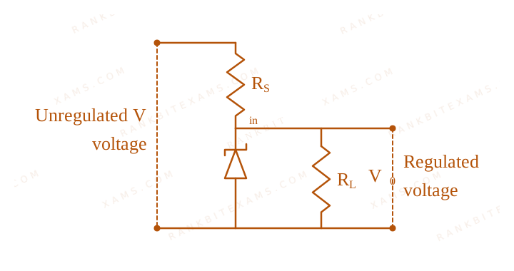
The following diagram shows a Zener diode as a voltage regulator. The Zener diode is rated at VZ = 5V$V_{Z} = 5V$ and the desired current in load is 5 mA. The unregulated voltage source can supply up to 25V. Considering the Zener diode can withstand four times of the load current, the value of resistor RS$R_{S}$ (shown in circuit) should be ____ Ω$\Omega$.
Circuit containing unregulated voltage, series resistor Rs, Zener diode, and load resistor.
The question is dropped by the examination authority, meaning there was an anomaly in data or multiple correct interpretations, likely due to imprecise wording regarding the maximum source voltage and the exact safe current rating. In a nominal calculation, I_Zmax = 4 × 5 mA = 20 mA$I_{Z_{\text{max}}} = 4 \times 5 \text{ mA} = 20 \text{ mA}$. Total current I = 25 mA$I = 25 \text{ mA}$. RS = (25 - 5) / (25 × 10⁻³) = 800Ω$R_{S} = (25 - 5) / (25 \times 10^{-3}) = 800\Omega$, which is not in the options.
Step 1: Final Conclusion
Question Dropped.
Pattern Recognition
Sees: "Question Dropped" → This often occurs when mathematical data maps to none of the provided MCQs.
Chapter Mix
Class 12 Physics: Semiconductor Electronics: Materials, Devices and Simple Circuits
Q38jee_main_2026_23_january_eveningLogic Gates
For the given logic gate circuit, which of the following is the correct truth table?
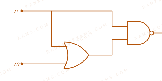
Circuit schematic containing an OR gate and a NAND gate.
A.
n
m
z
0
0
1
0
1
0
1
1
0
1
0
0
B.
n
m
z
0
0
0
0
1
1
1
1
0
1
0
1
C.
n
m
z
0
0
1
0
1
0
1
1
1
1
0
0
D.
n
m
z
0
0
1
0
1
1
1
1
0
1
0
0
Solution
Related Formula
Boolean Algebra rules:
A + AB = A$A + AB = A$A · A = A$A \cdot A = A$
NAND Gate: Z = X · Y$Z = \overline{X \cdot Y}$
Core Logic
Gate 1 (Bottom): This is an OR gate with inputs n$n$ and m$m$.
Output = n + m$n + m$
Gate 2 (Top): This is a NAND gate. Its inputs are direct n$n$ and the output of the OR gate (n + m$n + m$).
Output z = n · (n + m)$z = \overline{n \cdot (n + m)}$
Step 1: Simplify the Boolean Expression
First, expand the inner term:
n · (n + m) = (n · n) + (n · m)$$n \cdot (n + m) = (n \cdot n) + (n \cdot m)$$
Since n · n = n$n \cdot n = n$, this becomes:
n + n · m = n(1 + m) = n · 1 = n$$n + n \cdot m = n(1 + m) = n \cdot 1 = n$$
So the overall output is:
z = n · (n + m) = n$$z = \overline{n \cdot (n + m)} = \overline{n}$$
Step 2: Construct the Truth Table
Since z = n$z = \overline{n}$, the output z$z$ only depends on n$n$ and is its exact inverse.
When n=0, m=0 z=1$n=0, m=0 \implies z=1$
When n=0, m=1 z=1$n=0, m=1 \implies z=1$
When n=1, m=1 z=0$n=1, m=1 \implies z=0$
When n=1, m=0 z=0$n=1, m=0 \implies z=0$
Pattern Recognition
Always simplify the Boolean expression using standard absorption laws (like A(A+B) = A$A(A+B) = A$) before manually evaluating every row. It saves significant time.
Chapter Mix
Class 12 Physics: Semiconductor Electronics
More Semiconductor Electronics: Materials, Devices and Simple Circuits Questions — jee_main_2025_24_jan_morning
Practice past-year questions one chapter at a time. Pick an exam → subject → chapter and get every PYQ for that topic — pulled together from all past papers — with the chapter's key formulas alongside.