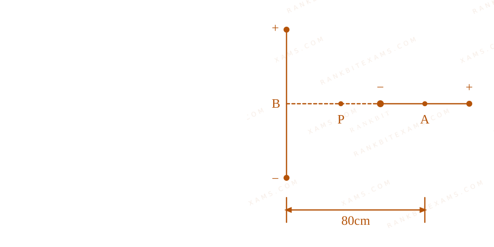
Two shorts dipoles(A, B)$(A, B)$ , A having charges ± 2μ C$\pm 2\mu C$ and length 1 cm and B having charges ± 4μ C$\pm 4\mu C$ and length 1 cm are placed with their centres 80 cm apart as shown in the figure. The electric field at a point P, equi-distant from the centres of both dipoles is ____ N/C.
Configuration of two short electric dipoles and an equidistant point P.
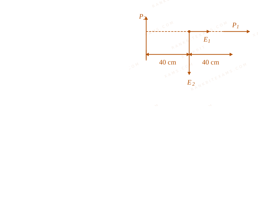
Configuration of two short electric dipoles and an equidistant point P.
Point P is at a distance of r = 40 cm = 0.4 m$r = 40 \, \mathrm{cm} = 0.4 \, \mathrm{m}$ from the centre of both dipoles.
For dipole A, point P lies on the axial line.
For dipole B, point P lies on the equatorial line.
Wait, the orientation in the figure sets the directions. From the diagram, A is oriented left-to-right (minus to plus) so E₁$\vec{E}_1$ on its axis is along + i$+\hat{i}$ or - i$-\hat{i}$ depending on precise placement. Based on standard convention:
Identify the relationship of the observation point to each dipole (axial vs equatorial). The axial field has a factor of 2, while the equatorial does not. Vector addition is mandatory since the fields are perpendicular.
Keywords:#two shorts dipoles#JEE Main 2026 Evening Q31#Electrostatics JEE Main 2026#Electric Dipole JEE Main 2026#two short dipoles#electric field P#equidistant point
More Electrostatics Previous-Year Questions — Page 8
Q9jee_main_2025_08_april_eveningElectric Charge and Properties
Two metal spheres of radius R$R$ and 3R$3R$ have same surface charge density σ$\sigma$. If they are brought in contact and then separated, the surface charge density on smaller and bigger sphere becomes σ₁$\sigma_{1}$ and σ₂$\sigma_{2}$, respectively. The ratio σ₁σ₂$\frac{\sigma_{1}}{\sigma_{2}}$ is:
A.(1)/(9)$\frac{1}{9}$
B.9$9$
C.(1)/(3)$\frac{1}{3}$
D.3$3$
Solution
Related Formula
V = (σ r)/(ε₀)$$V = \frac{\sigma r}{\varepsilon_0}$$
where,
V$V$ = electrostatic potential of a conducting sphere
σ$\sigma$ = surface charge density
r$r$ = radius of the sphere
Core Logic
For any conducting sphere, the potential on its surface is related to its surface charge density by:
When the two spheres of radii r₁ = R$r_1 = R$ and r₂ = 3R$r_2 = 3R$ are brought into contact, charge flows between them until they reach an identical electric potential:
V₁ = V₂$V_1 = V_2$
Step 1: Ratio Calculation
Equate the potentials of the two spheres after separation:
Sees: "Conducting spheres brought in contact" → Electric potentials become equal: V₁ = V₂$V_1 = V_2$.
Shortcut: Since V ∝ σ r$V \propto \sigma r$, equal potential directly implies σ₁ r₁ = σ₂ r₂$\sigma_1 r_1 = \sigma_2 r_2$. Thus, the ratio of final densities is simply the inverse ratio of their radii: (σ₁)/(σ₂) = (r₂)/(r₁) = (3)/(1) = 3$\frac{\sigma_1}{\sigma_2} = \frac{r_2}{r_1} = \frac{3}{1} = 3$. This bypasses computing the individual final charges entirely! ✓
Chapter Mix
Class 12 Physics: Electrostatics
Q23jee_main_2025_08_april_eveningCapacitance
Space between the plates of a parallel plate capacitor of plate area 4~cm²$4\mathrm{~cm}^{2}$ and separation of (d) 1.77~mm$1.77\mathrm{~mm}$, is filled with uniform dielectric materials with dielectric constants (3$3$ and 5$5$) as shown in figure. Another capacitor of capacitance 7.5~pF$7.5\mathrm{~pF}$ is connected in parallel with it. The effective capacitance of this combination is ________ ~pF$\mathrm{~pF}$.
This diagram shows a parallel plate capacitor filled with two layers of dielectric constant k=5 and k=3, each having thickness d/2.
(Given ε₀ = 8.85× 10⁻¹²~F/m$\varepsilon_0 = 8.85\times 10^{-12}\mathrm{~F/m}$)
Numerical Answer.Answer: 15 to 15
Solution
Related Formula
C = k (ε₀ A)/(t)$$C = k \frac{\varepsilon_0 A}{t}$$1Cₛₑᵣᵢₑₛ = (1)/(C₁) + (1)/(C₂)$$\frac{1}{C_{\text{series}}} = \frac{1}{C_1} + \frac{1}{C_2}$$Cparallel = Ceq + Cₚ$$C_{\text{parallel}} = C_{\text{eq}} + C_p$$
Core Logic
The dielectrics k₁ = 5$k_1 = 5$ and k₂ = 3$k_2 = 3$ split the capacitor separation horizontally into two layers, each of thickness (d)/(2)$\frac{d}{2}$. Thus, they act as two capacitors connected in series:
Sees: Dielectric boundary parallel to the plates → Series capacitors.
Trap: Don't treat horizontally split layers as parallel; split in distance d$d$ means series, while split in area A$A$ means parallel.
Shortcut: Notice (35.4)/(1.77)$\frac{35.4}{1.77}$ is exactly 20$20$. This makes the numerical calculations incredibly clean! ✓
Chapter Mix
Class 12 Physics: Electrostatics
Q3jee_main_2025_29_jan_eveningElectric Dipole in Uniform Electric Field
An electric dipole is placed at a distance of 2~cm$2\mathrm{~cm}$ from an infinite plane sheet having positive charge density σ₀$\sigma_0$. Choose the correct option from the following.
The diagram illustrates an electric dipole with charges -q and +q aligned parallel to an infinite plane sheet of positive charge density.
A.Torque on dipole is zero and net force is directed away from the sheet.$\text{Torque on dipole is zero and net force is directed away from the sheet.}$
B.Torque on dipole is zero and net force acts towards the sheet.$\text{Torque on dipole is zero and net force acts towards the sheet.}$
C.Potential energy of dipole is minimum and torque is zero.$\text{Potential energy of dipole is minimum and torque is zero.}$
D.Potential energy and torque both are maximum$\text{Potential energy and torque both are maximum}$
Solution
Related Formula
E = (σ₀)/(2ε₀)$$E = \frac{\sigma_0}{2\epsilon_0}$$τ = p × E$$\vec{\tau} = \vec{p} \times \vec{E}$$U = - p · E$$U = -\vec{p} \cdot \vec{E}$$
Core Logic
An infinite plane sheet produces a uniform electric field E$\vec{E}$ directed normally away from the sheet.
As shown in the image layout, the dipole moment vector p$\vec{p}$ (pointing from -q$-q$ to +q$+q$) is oriented parallel to the electric field vectors E$\vec{E}$:
Since the electric field is uniform, the force on +q$+q$ balances the force on -q$-q$, meaning Fₙₑₜ = 0$F_{\text{net}} = 0$.
Pattern Recognition
When a dipole aligns perfectly with a uniform electric field (p ∥ E$\vec{p} \parallel \vec{E}$), it reaches stable equilibrium. Stable equilibrium fundamentally means minimum potential energy (U = -pE$U = -pE$) and zero torque.
Chapter Mix
Class 12 Physics: Electrostatics
Q5jee_main_2025_29_jan_eveningGauss's Law and Flux
A point charge causes an electric flux of -2 × 10⁴ ~Nm²C⁻¹$-2 \times 10^{4} \mathrm{~Nm}^{2}\mathrm{C}^{-1}$ to pass through a spherical Gaussian surface of 8.0~cm$8.0\mathrm{~cm}$ radius, centred on the charge. The value of the point charge is :
(Given ε₀ = 8.85 × 10⁻¹² ~C²N⁻¹m⁻²)$(\mathrm{Given } \epsilon_{0} = 8.85 \times 10^{-12} \mathrm{~C}^{2}\mathrm{N}^{-1}\mathrm{m}^{-2})$
where,
φ$\phi$ = net electric flux through the closed surface
qenclosed$q_{\text{enclosed}}$ = net charge enclosed by the surface
ε₀$\epsilon_0$ = permittivity of free space
Core Logic
According to Gauss's Law, the total electric flux through a closed surface depends only on the charge enclosed inside it, completely independent of the radius of the surface.
Distractor alert: The radius (8.0~cm$8.0\mathrm{~cm}$) is extra data meant to mislead. Gauss's flux depends entirely on the magnitude of the enclosed charge, not the physical surface area configuration.
Chapter Mix
Class 12 Physics: Electrostatics
Q14jee_main_2025_29_jan_eveningSharing of Charges and Loss of Energy
A capacitor, C₁ = 6$C_1 = 6\mu\mathrm{F}$ is charged to a potential difference of V₀ = 5V$V_0 = 5\mathrm{V}$ using a 5V$5\mathrm{V}$ battery. The battery is removed and another capacitor, C₂ = 12$C_2 = 12\mu\mathrm{F}$ is inserted in place of the battery. When the switch 'S' is closed, the charge flows between the capacitors for some time until equilibrium condition is reached. What are the charges (q₁$(q_1$ and q₂)$q_2)$ on the capacitors C₁$C_1$ and C₂$C_2$ when equilibrium condition is reached.
The circuit diagram displays two capacitors C1 and C2 with a switch S used to establish parallel connectivity between them.
Uncharged capacitor C₂$C_2$ holds q₂' = 0$q_2' = 0$.
The circuit diagram displays two capacitors C1 and C2 with a switch S used to establish parallel connectivity between them.
Redistribution at Equilibrium:
Closing the switch causes parallel redistribution until they reach a common potential Vc$V_c$:
The circuit diagram displays two capacitors C1 and C2 with a switch S used to establish parallel connectivity between them.
Hence, the charges are 10$10\mu\mathrm{C}$ and 20$20\mu\mathrm{C}$ respectively.
Pattern Recognition
For parallel combination setups, the final charge splits in the exact direct ratio of their capacitances: q₁ : q₂ = C₁ : C₂ = 6 : 12 = 1 : 2$q_1 : q_2 = C_1 : C_2 = 6 : 12 = 1 : 2$. Out of 30$30\mu\mathrm{C}$, the breakdown must cleanly be 10$10\mu\mathrm{C}$ and 20$20\mu\mathrm{C}$.
Chapter Mix
Class 12 Physics: Electrostatic Potential and Capacitance
More Electrostatics Questions — jee_main_2026_23_january_evening
Practice past-year questions one chapter at a time. Pick an exam → subject → chapter and get every PYQ for that topic — pulled together from all past papers — with the chapter's key formulas alongside.