JEE Main · Physics → Steady

System of Particles and Rotational Motion appeared 58 times across 3 years — 6.7% of Physics. This question is from Centre of Mass.

Year 2026 2025 2024 Total
Questions 20 27 11 58

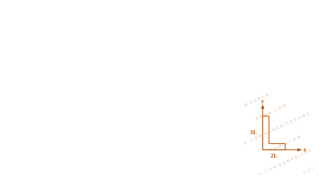
A rod of length 5 ~L is bent right angle keeping one side length as 2 ~L .
L-shaped bent rod geometry for Q6 - JEE Main 2025 Morning
Diagram of an L-shaped rod aligned with the x and y axes, with lengths 2L and 3L respectively.
The position of the centre of mass of the system : (Consider L = 10cm )

Solution & Explanation

Related Formula

For a continuous system modeled as discrete point masses located at their respective centers of mass:

xcom = (m₁x₁ + m₂x₂)/(m₁ + m₂) ycom = (m₁y₁ + m₂y₂)/(m₁ + m₂)
Core Logic

Let the uniform linear mass density of the rod be λ.

  • Total length is 5L.
  • One segment of length 2L lies on the x-axis. Its mass is 2m = λ(2L) and its center of mass is at (L, 0).
  • The remaining segment of length 3L lies on the y-axis. Its mass is 3m = λ(3L) and its center of mass is at (0, 1.5L).
Step 1: Calculate COM Coordinates

Find the coordinates of the system's center of mass:

xcom = (2m(L) + 3m(0))/(2m + 3m) = (2L)/(5) = 0.4L ycom = (2m(0) + 3m(1.5L))/(2m + 3m) = (4.5L)/(5) = 0.9L

Given L = 10 ~cm:

xcom = 0.4 × 10 = 4 ~cm ycom = 0.9 × 10 = 9 ~cm
Step 2: Vector Form

Expressing in vector notation:

rcom = 4 i + 9 j
Pattern Recognition

Sees: L-shaped rod formed by bending a total length Ltotal. Shortcut: Treat each arm as a point mass at its geometric midpoint. For segments of ratio 2:3, the COM divides the distance between their midpoints in the inverse ratio 3:2 closer to the heavier segment on the y-axis.

Chapter Mix

Class 11 Physics: System of Particles and Rotational Motion

Vector resolution of bent rod midpoints
Diagram of an L-shaped rod aligned with the x and y axes, with lengths 2L and 3L respectively.

Reference Study Guides

More System of Particles and Rotational Motion Previous-Year Questions — Page 7

Q15 jee_main_2025_29_jan_evening Angular Momentum of a System of Particles
Three equal masses m are kept at vertices (A, B, C) of an equilateral triangle of side a in free space. At t = 0 , they are given an initial velocity VA = V₀ AC , VB = V₀ BA and VC = V₀ CB . Here, AC, CB and BA are unit vectors along the edges of the triangle. If the three masses interact gravitationally, then the magnitude of the net angular momentum of the system at the point of collision is:
Angular Momentum of a System of Particles diagram for Q15 - JEE Main 2025 Evening
The graphic exhibits three mass particles at the vertices of an equilateral triangle with velocity vectors pointed along the cyclic boundary directions.
  • A. (1)/(2) ~a ~mV₀
  • B. 3amV₀
  • C. √(3)2 ~a ~mV₀
  • D. (3)/(2) ~a ~mV₀

Solution

Related Formula
L = Σ ( rᵢ × m vᵢ) τₑₓₜ = d Ldt
Core Logic

Since the three masses interact purely through mutual internal gravitational forces, the net external torque acting on the system about any central reference point is zero:

τₑₓₜ = 0 Linitial = Lfinal

Let us compute the total angular momentum about the centroid of the equilateral triangle:

Angular Momentum Calculation Geometry diagram for Q15 - JEE Main 2025 Evening
The graphic exhibits three mass particles at the vertices of an equilateral triangle with velocity vectors pointed along the cyclic boundary directions.
From trigonometry, the perpendicular distance from the centroid to the velocity vector along any edge is:

r⊥ = a2√(3)

The initial angular momentum for one mass about the centroid is L₁ = m V₀ r⊥. Since all three particles move cyclically in the same direction, their angular momenta reinforce cleanly:

Lₙₑₜ = 3 · (m V₀ a2√(3)) = 32√(3) m V₀ a = √(3)2 a m V₀

By conservation of angular momentum, this configuration value remains unchanged up to the point of collision.

Pattern Recognition

Mutual internal central forces can never alter the angular momentum of a system. Hence, the solution completely reduces to measuring the static configuration values at t=0 about the center of mass symmetry.

Chapter Mix

Class 11 Physics: System of Particles and Rotational Motion Class 11 Physics: Gravitation

Q19 jee_main_2025_28_jan_morning Centre of Mass of Continuous Mass Distribution
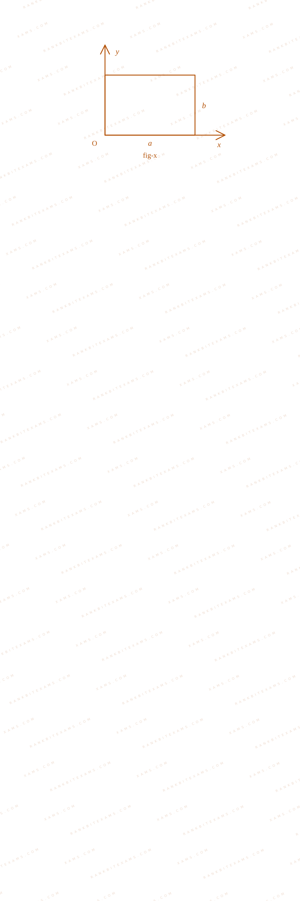
The centre of mass of a thin rectangular plate (fig - x) with sides of length a and b, whose mass per unit area (σ) varies as σ = (σ₀x)/(ab) (where σ₀ is a constant), would be
Centre of Mass diagram for Q19 - JEE Main 2025 Morning
A thin plate with variable linear density coordinates mapped across an XY grid system.
  • A. ((2)/(3) a, (b)/(2))
  • B. ((2)/(3) a, (2)/(3) b)
  • C. ((a)/(2),(b)/(2))
  • D. ((1)/(3) a, (b)/(2))

Solution

Core Logic

Since density σ is independent of the y-coordinate, the vertical center of mass resolves directly by symmetry:

ycm = b2

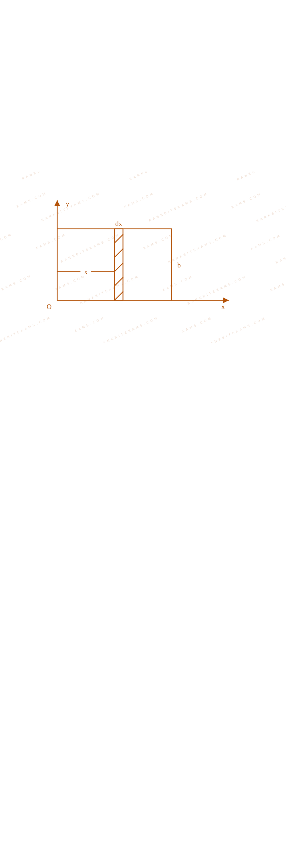
Integration element tracking for continuous mass distribution on Q19
A thin plate with variable linear density coordinates mapped across an XY grid system.

To find the horizontal center of mass, evaluate the continuous mass integral along the x-axis:

xcm = ∫₀a x dm∫₀a dm = ∫₀a x ( σ₀ xab) b dx∫₀a ( σ₀ xab) b dx xcm = ∫₀a x² dx∫₀a x dx = [ x³3 ]₀a[ x²2 ]₀a = a³ / 3a² / 2 = 2a3
Step 1: Final Position Coordinates

The center of mass coordinates are ((2)/(3) a, b2), which matches option (1).

Pattern Recognition

When density varies linearly with position (σ ∝ x), the mass distribution shifts outward, moving the center of mass from the geometric midpoint a2 to the (2)/(3)a mark.

Chapter Mix

Class 11 Physics: System of Particles and Rotational Motion

Q22 jee_main_2025_28_jan_morning Moment of Inertia
The moment of inertia of a solid disc rotating along its diameter is 2.5 times higher than the moment of inertia of a ring rotating in similar way. The moment of inertia of a solid sphere which has same radius as the disc and rotating in similar way, is n times higher than the moment of inertia of the given ring. Here, n = _____. Consider all the bodies have equal masses.
Numerical Answer. Answer: 4 to 4

Solution

Related Formula
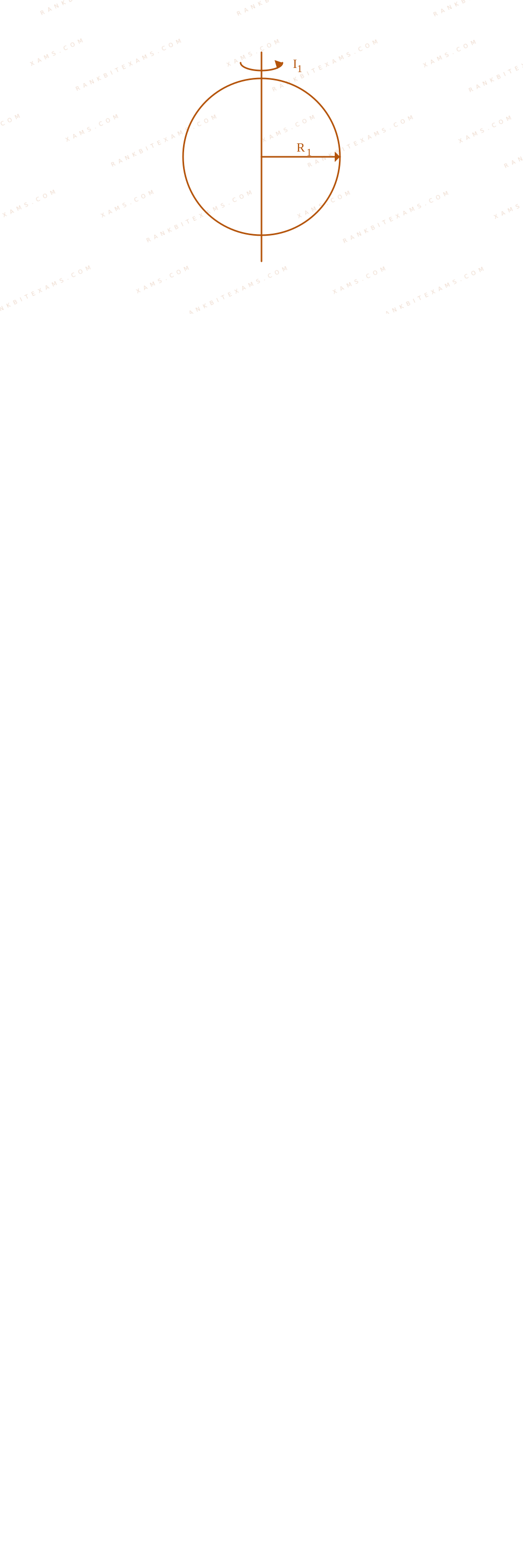
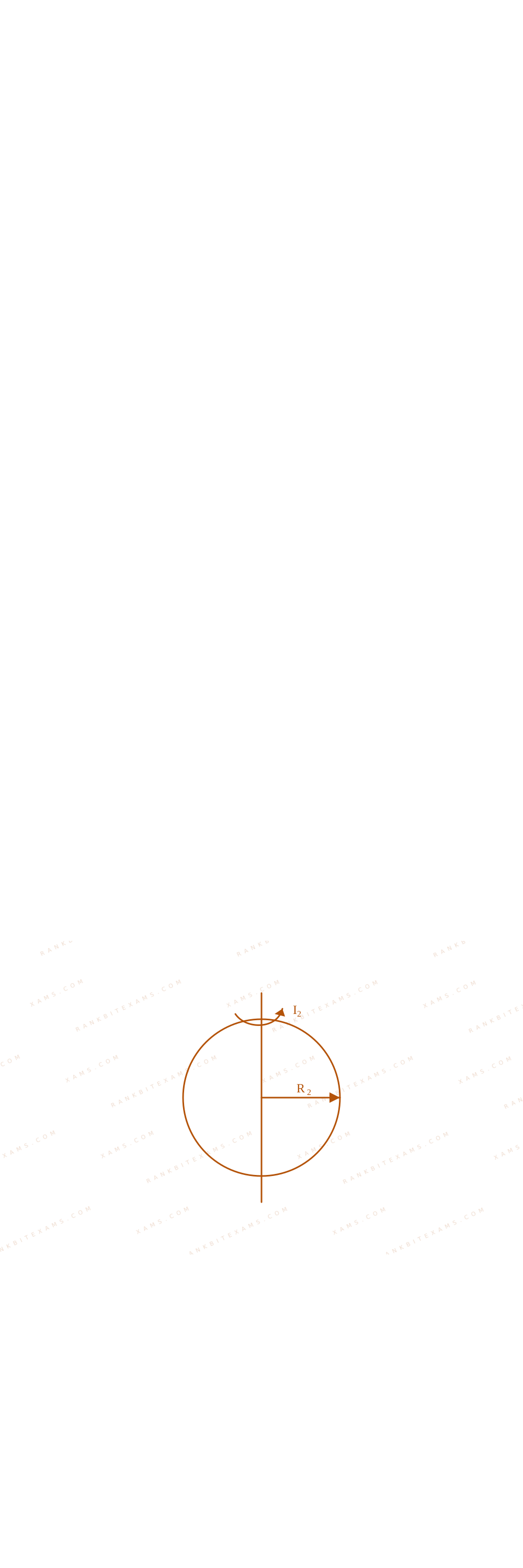
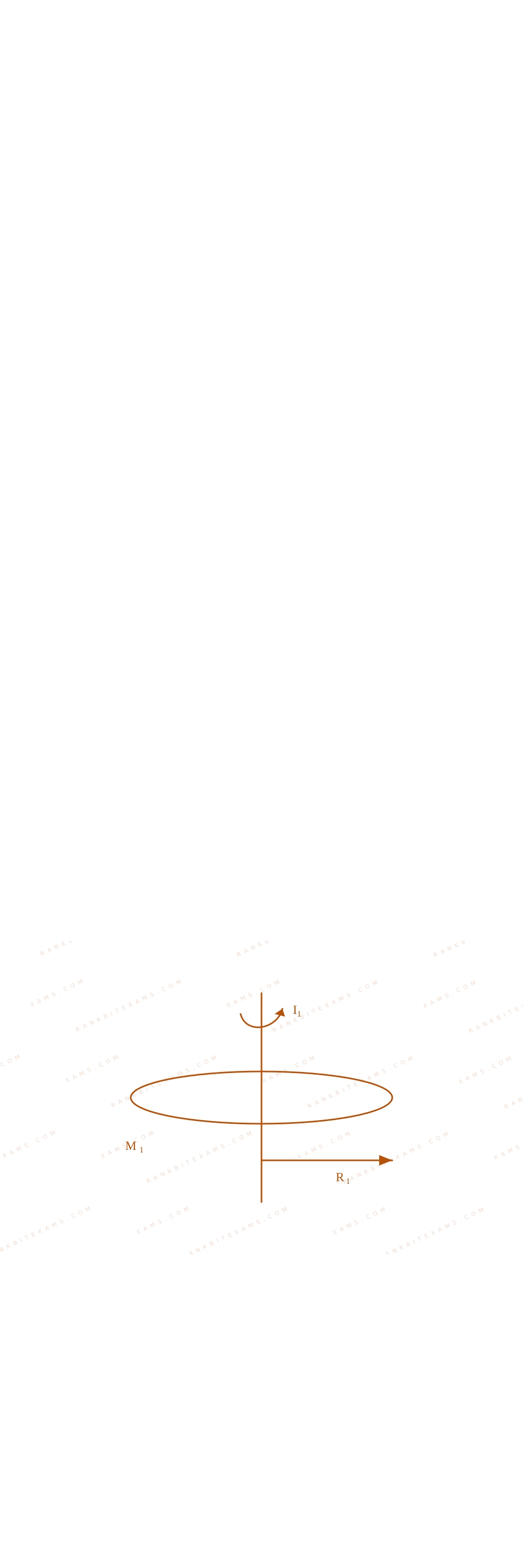
Idisc = MR₁²4, Iring = MR₂²2, Isphere = 2MR₁²5
Core Logic

Let's list the relevant moment of inertia formulas based on their rotation axes:

Moment of inertia axial comparison steps for Q22

Moment of inertia axial comparison steps for Q22

Moment of inertia axial comparison steps for Q22

From the given problem statements:

IdiscIring = 2.5 MR₁²4 MR₂²2 = (5)/(2) R₁²R₂² = 5

Now, evaluating the second geometric layout ratio:

IsphereIring = n 2MR₁²5 MR₂²2 = n 4R₁²5R₂² = n

Substituting our radius parameter (R₁²R₂² = 5):

n = (4)/(5) · 5 = 4
Step 1: Final Value Conclusion

The scale value parameter is found to be:

n = 4

Pattern Recognition

Be careful with rotation axis descriptions. Disc and ring components rotating along their structural diameter axes use values that are half of their standard perpendicular planar formulas.

Chapter Mix

Class 11 Physics: System of Particles and Rotational Motion

Q24 jee_main_2025_28_jan_morning Moment of Inertia
Two iron solid discs of negligible thickness have radii R₁ and R₂ and moment of inertia I₁ and I₂ , respectively. For R₂ = 2R₁ , the ratio of I₁ and I₂ would be 1 / x , where x =
Numerical Answer. Answer: 16 to 16

Solution

Core Logic

Since mass scales with the face surface area for discs of identical thickness and material composition:

M = σ · π R² M ∝ R²

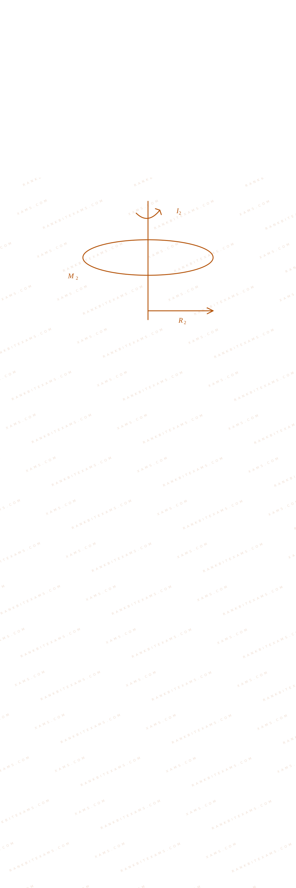
Disk mass allocation scaling profile diagram for Q24

Disk mass allocation scaling profile diagram for Q24

M₁ = M₀, M₂ = σ π (2R₁)² = 4M₀

The moment of inertia formula for a disc is:

mathrmI = (1)/(2)MR² I ∝ MR² ∝ R⁴

Calculating the ratio for the given radii configuration:

I₁I₂ = M₁ R₁²M₂ R₂² = M₀ · R₁²4M₀ · (2R₁)² = (1)/(16)
Step 1: Value Convergence

Comparing this fraction to 1/x yields:

x = 16

Pattern Recognition

For 2D uniform laminar objects, scaling the radius changes both the mass factor (by R²) and the distribution distance (by R²), resulting in an overall R⁴ dependency rule.

Chapter Mix

Class 11 Physics: System of Particles and Rotational Motion

Q10 jee_main_2025_03_april_morning Rolling Without Slipping
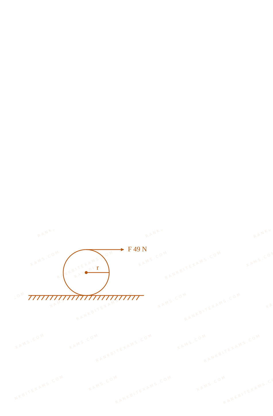
A force of 49~N acts tangentially at the highest point of a sphere (solid) of mass 20~kg, kept on a rough horizontal plane. If the sphere rolls without slipping, then the acceleration of the center of the sphere is:
Solid sphere with tangential force at top point for Q10
A schematic of a solid sphere of mass m resting on a horizontal plane with a force F pointing horizontally to the right at the highest point.
  • A. 3.5~m/s²
  • B. 0.35~m/s²
  • C. 2.5~m/s²
  • D. 0.25~m/s²

Solution

Related Formula

Torque equation about the instantaneous center of zero velocity (bottom contact point P):

τP = IP α

For a solid sphere, the moment of inertia about the center is Ic = (2)/(5)MR². By the parallel axis theorem:

IP = Ic + MR² = (7)/(5)MR²
Core Logic

Since the sphere rolls without slipping, we can conveniently write the torque equation about the lowest point of contact P because static friction passes through this point and exerts zero torque.

  • Distance from point P to the top highest point is 2R.
  • Tangential force F = 49~N.
  • Mass of solid sphere, M = 20~kg.
τP = F × 2R

Substitute τP and IP into the torque equation:

F × 2R = ((7)/(5)MR²) α
Step 1: Solving for Linear Acceleration

For pure rolling, the acceleration of the center of mass a is related to angular acceleration α by a = Rα:

2F R = (7)/(5)MR² ((a)/(R)) 2F = (7)/(5) M a a = (10F)/(7M)

Substitute the numerical values (F = 49~N and M = 20~kg):

a = (10 × 49)/(7 × 20) = (490)/(140) = 3.5~m/s²
Step 2: Analysis of Friction Force Direction

Let's write force equations to verify consistency: F + f = M a

49 + f = 20 × 3.5 = 70 f = 21~N

Since f is positive, static friction acts in the forward direction. Rolling without slipping is fully maintained since the required static friction coefficient is well within realistic limits.

Pattern Recognition

Calculating torque about the bottom contact point is a powerful shortcut for rolling-without-slipping questions! It completely bypasses having to guess or set up equations for the friction direction.

Chapter Mix

Class 11 Physics: System of Particles and Rotational Motion
More System of Particles and Rotational Motion Questions — jee_main_2025_07_april_morning

Practice all System of Particles and Rotational Motion previous-year questions →

Rankbit System
JEE Physics: Waves (+15.5%) | Electrostatics: Concentric Shells (-29.7%) | Modern Physics: Photoelectric Clones (+34.2%) | Mathematics: Definite Integrals (+18.1%) | Chemistry: Coordination Splitting (-11.4%) | JEE Physics: Waves (+15.5%) | Electrostatics: Concentric Shells (-29.7%) | Modern Physics: Photoelectric Clones (+34.2%) | Mathematics: Definite Integrals (+18.1%) | Chemistry: Coordination Splitting (-11.4%)