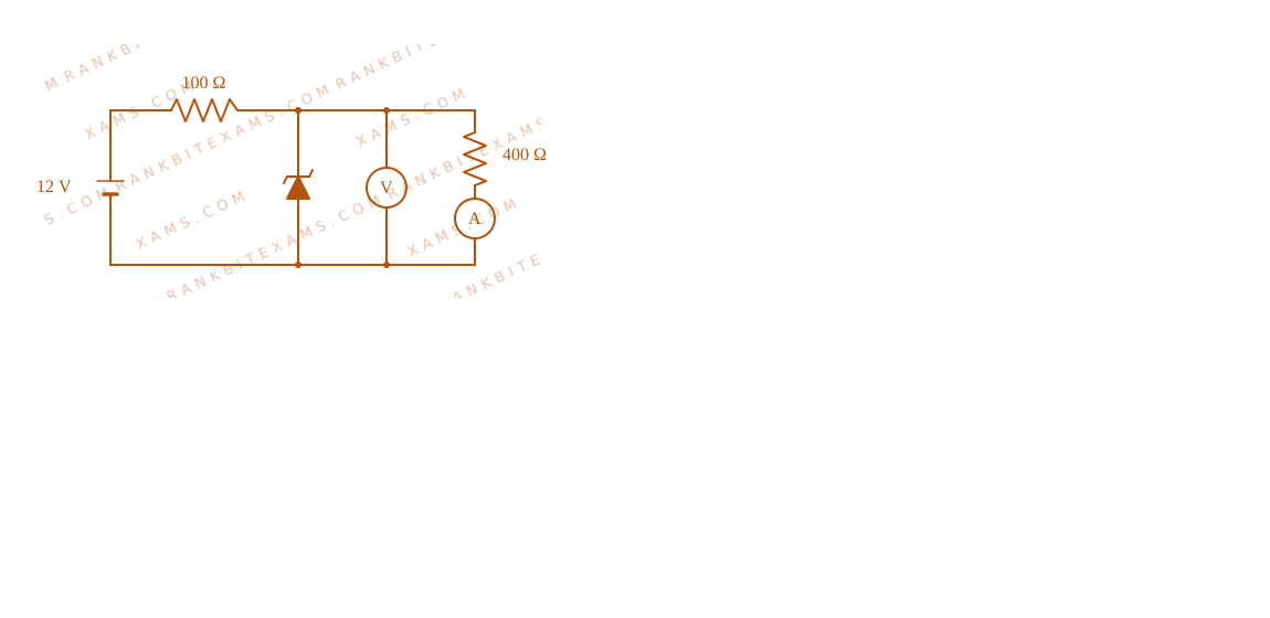
In the following circuit, the reading of the ammeter will be (Take Zener breakdown voltage = 4 V)
Zener regulator circuit for Q11 - JEE Main 2025 Morning
A schematic showing a 12V supply connected to a series 100 ohm resistor, which then branches into a parallel Zener diode and a 400 ohm resistor in series with an ammeter.

Zener regulator circuit for Q11 - JEE Main 2025 Morning
A schematic showing a 12V supply connected to a series 100 ohm resistor, which then branches into a parallel Zener diode and a 400 ohm resistor in series with an ammeter.

Solution & Explanation

Related Formula

Voltage division across load RL with series resistance Rₛ without Zener regulation:

VL = Vᵢₙ ( (RL)/(Rₛ + RL) )

If VL > Vz, the Zener diode enters breakdown, and potential across the parallel load is clamped at VL = Vz.

Core Logic

Verify if Zener diode operates in the breakdown region:

  • Vᵢₙ = 12 ~V
  • Rₛ = 100 Ω
  • RL = 400 Ω
  • Calculate the unregulated voltage:

V₁ = 12 × ( (400)/(100 + 400) ) = 12 × (4)/(5) = 9.6 ~V

Since V₁ > Vz (9.6 ~V > 4 ~V), breakdown occurs, and the parallel branch voltage is fixed at Vz = 4 ~V.

Step 1: Calculate Branch Current

The voltage across the 400 Ω load resistor (which is in series with the ammeter) is locked at 4 ~V.

The current I through the ammeter is:

I = (Vz)/(RL) = 4 ~V400 Ω = 10⁻² ~A = 10 ~mA
Pattern Recognition

Sees: Parallel Zener diode configuration. Shortcut: Always calculate the open-circuit load voltage first. If it exceeds Vz, use Vz as the branch potential. The branch current is simply Vz / RL. Here, 4 / 400 = 10 ~mA.

Chapter Mix

Class 12 Physics: Semiconductor Electronics: Materials, Devices and Simple Circuits

Phasor and load lines representation for Zener breakdown state
A schematic showing a 12V supply connected to a series 100 ohm resistor, which then branches into a parallel Zener diode and a 400 ohm resistor in series with an ammeter.

More Semiconductor Electronics: Materials, Devices and Simple Circuits Previous-Year Questions — Page 7

Q49 jee_main_2024_31_jan_evening Logic Gates
The output of the given circuit diagram is
Logic Gates diagram for Q49 - JEE Main 2024 Evening
The image shows a logic circuit composed of NOT gates, OR gates, and a final NOR gate.
  • A.
    ABY
    000
    100
    010
    111
  • B.
    ABY
    000
    101
    011
    110
  • C.
    ABY
    000
    100
    010
    110
  • D.
    ABY
    000
    100
    011
    110

Solution

Related Formula

Boolean Algebra expressions for logic gates: NOT: A OR: A + B NOR: A + B

Core Logic

Analyze the paths from inputs A and B to the final output Y.

Logic Gates diagram for Q49 - JEE Main 2024 Evening
The image shows a logic circuit composed of NOT gates, OR gates, and a final NOR gate.

Step 1: Intermediate Signals

Top OR gate inputs: A directly, and B inverted (B). Top OR gate output: A + B

Bottom OR gate inputs: A inverted (A), and B directly. Bottom OR gate output: A + B

Step 2: Final Gate Evaluation

The final gate is a NOR gate taking the two intermediate outputs as its inputs.

Y = (A + B) + ( A + B)

Notice that the inner sum simplifies cleanly:

(A + A) + (B + B)

Since A + A = 1 and B + B = 1, the inner term is 1 + 1 = 1.

Y = 1 = 0
Step 3: Conclusion

The output Y is always 0 regardless of the inputs A and B. Checking the truth tables, only option 3 satisfies Y=0 for all conditions.

Pattern Recognition

When a Boolean expression groups a variable and its exact complement together in an OR configuration (A and A), the result instantly hits logic 1. Feeding 1 into any NOR gate guarantees a 0 output universally.

Chapter Mix

Class 12 Physics: Semiconductor Electronics
Q jee_main_2024_31_jan_morning Logic Gates
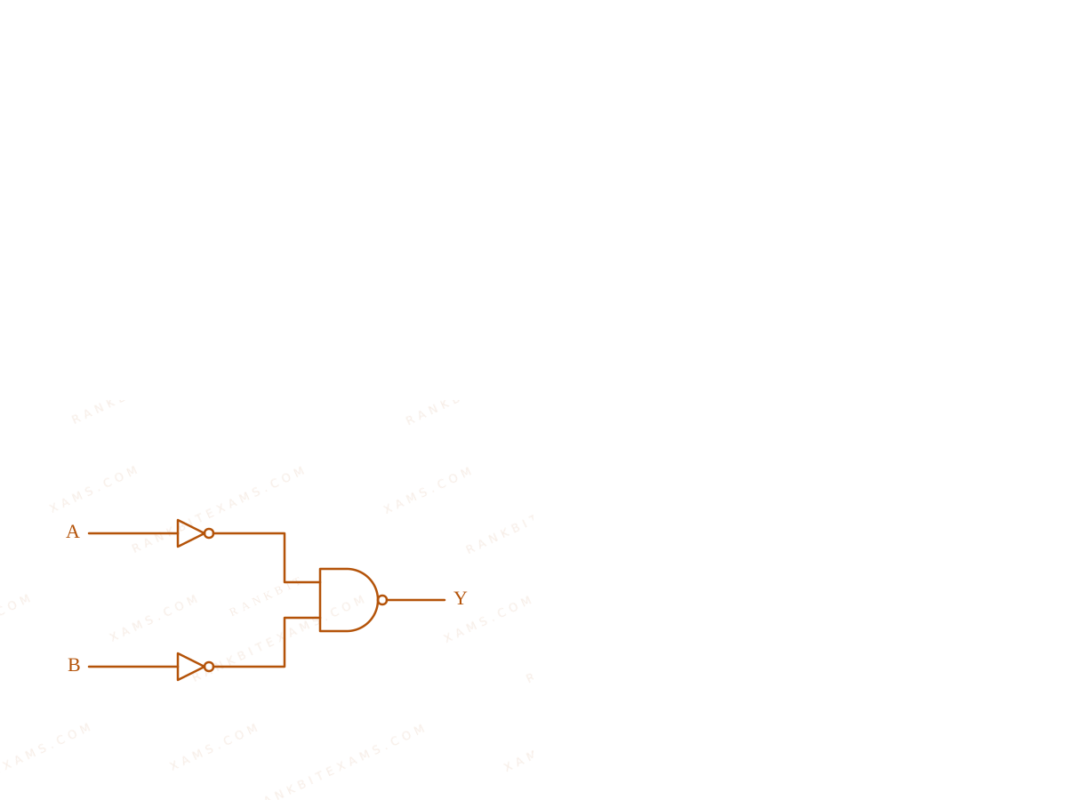
Identify the logic operation performed by the given circuit.
Logic Gates diagram for Q32 - JEE Main 2024 Morning
Two inputs passing through NOT gates before entering a NAND gate.
  • A. NAND
  • B. NOR
  • C. OR
  • D. AND

Solution

Related Formula
Y = A · B (NAND) Y = A + B (De Morgan's)
Core Logic

The inputs A and B are first passed through individual NOT gates (made from tied-input NAND gates or standard NOT gates). The outputs become A and B.

These are then fed into a NAND gate. The final output Y is:

Y = A · B

Applying De-Morgan's Law:

Y = A + B

Y = A + B

This represents an OR operation.

Pattern Recognition

Bubbled inputs on a NAND gate convert it directly into an OR gate via De-Morgan's laws. (Bubbled NAND = OR).

Chapter Mix

Class 12 Physics: Semiconductor Electronics

More Semiconductor Electronics: Materials, Devices and Simple Circuits Questions — jee_main_2025_07_april_morning

Practice all Semiconductor Electronics: Materials, Devices and Simple Circuits previous-year questions →

Rankbit System
JEE Physics: Waves (+15.5%) | Electrostatics: Concentric Shells (-29.7%) | Modern Physics: Photoelectric Clones (+34.2%) | Mathematics: Definite Integrals (+18.1%) | Chemistry: Coordination Splitting (-11.4%) | JEE Physics: Waves (+15.5%) | Electrostatics: Concentric Shells (-29.7%) | Modern Physics: Photoelectric Clones (+34.2%) | Mathematics: Definite Integrals (+18.1%) | Chemistry: Coordination Splitting (-11.4%)