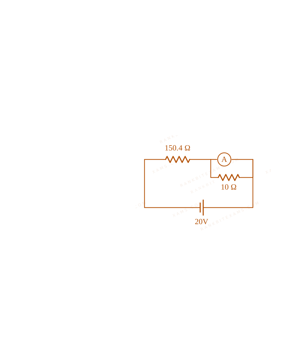
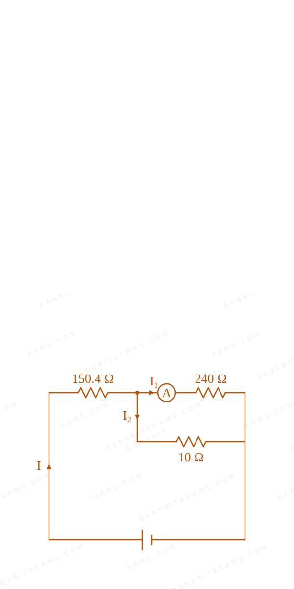
In the figure shown below, a resistance of 150.4Ω$150.4\Omega$ is connected in series to an ammeter A of resistance 240Ω$240\Omega$. A shunt resistance of 10Ω$10\Omega$ is connected in parallel with the ammeter. The reading of the ammeter is ________ mA$\mathrm{mA}$.
A circuit schematic containing a 20V battery connected in series with a 150.4 ohm resistor and a parallel combination of a 240 ohm ammeter and a 10 ohm shunt resistor.
Numerical Answer Type:
Enter a numerical valueAnswer: 5 to 5+4 marks
Solution & Explanation
Related Formula
Parallel combination of ammeter (RG = 240Ω$R_G = 240\Omega$) and shunt (S = 10Ω$S = 10\Omega$):
Therefore, the reading of the ammeter is 5~mA$5\mathrm{~mA}$.
A circuit schematic containing a 20V battery connected in series with a 150.4 ohm resistor and a parallel combination of a 240 ohm ammeter and a 10 ohm shunt resistor.A circuit schematic containing a 20V battery connected in series with a 150.4 ohm resistor and a parallel combination of a 240 ohm ammeter and a 10 ohm shunt resistor.
Pattern Recognition
Notice how nicely the numbers are set up in JEE Mains questions! The parallel combination of 240Ω$240\Omega$ and 10Ω$10\Omega$ yields exactly 9.6Ω$9.6\Omega$, which beautifully combines with 150.4Ω$150.4\Omega$ to form a perfect integer sum of 160Ω$160\Omega$. This tells you that your intermediate steps are absolutely correct!
Chapter Mix
Class 12 Physics: Current Electricity: Measuring Devices
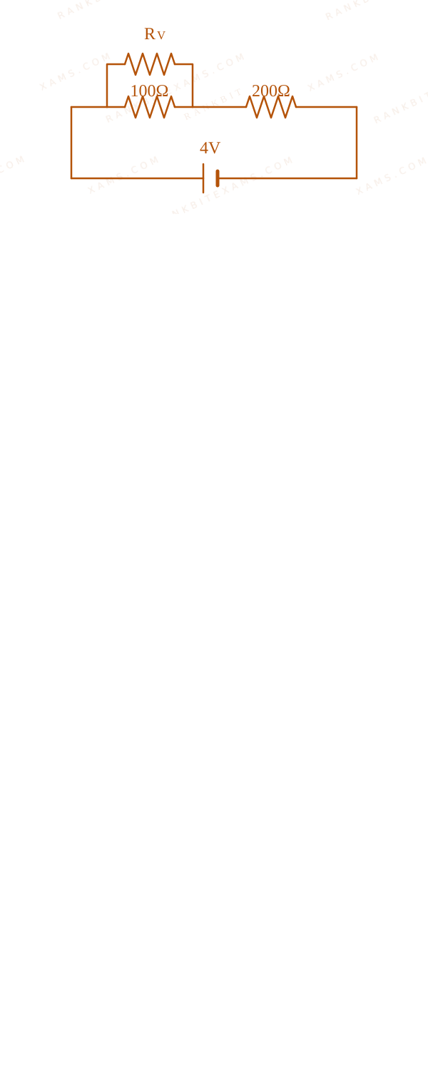
Two resistance of 100Ω$100\Omega$ and 200Ω$200\Omega$ are connected in series with a battery of 4 ~V$4 \mathrm{~V}$ and negligible internal resistance. A voltmeter is used to measure voltage across 100Ω$100\Omega$ resistance, which gives reading as 1 ~V$1 \mathrm{~V}$. The resistance of voltmeter must be ________ Ω$\Omega$.
Numerical Answer.Answer: 200 to 200
Solution
Related Formula
V = I Req$$V = I R_{\text{eq}}$$Rparallel = (R₁ R₂)/(R₁ + R₂)$$R_{\text{parallel}} = \frac{R_1 R_2}{R_1 + R_2}$$
Core Logic
Voltmeter Resistance diagram for Q60 - JEE Main 2024 Evening
The voltmeter has some internal resistance Rv$R_v$ and is connected in parallel with the 100Ω$100\Omega$ resistor.
The equivalent resistance of this parallel combination is Rₚ = (100 Rv)/(100 + Rv)$R_p = \frac{100 R_v}{100 + R_v}$.
This combination is in series with the 200Ω$200\Omega$ resistor. The total voltage applied is 4 ~V$4 \mathrm{~V}$.
Step 1: Set up Voltage Divider
The voltage across the parallel combination (the voltmeter reading) is 1 ~V$1 \mathrm{~V}$.
Therefore, the voltage across the 200Ω$200\Omega$ resistor must be 4 ~V - 1 ~V = 3 ~V$4 \mathrm{~V} - 1 \mathrm{~V} = 3 \mathrm{~V}$.
Using the voltage divider rule (or equating currents since they are in series):
If the voltage splits as 1V$1\mathrm{V}$ to 3V$3\mathrm{V}$, the resistances must be in a 1:3$1:3$ ratio. So Rₚ = 200 / 3$R_p = 200 / 3$. Equating 100 Rv / (100+Rv) = 200/3$100 R_v / (100+R_v) = 200/3$ instantly gives Rv = 200$R_v = 200$.
Chapter Mix
Class 12 Physics: Current Electricity
Q48jee_main_2024_30_january_eveningPower Dissipation in Resistors
When a potential difference V$V$ is applied across a wire of resistance R$R$, it dissipates energy at a rate W$W$. If the wire is cut into two halves and these halves are connected mutually parallel across the same supply, the energy dissipation rate will become:
A.1 / 4 W$1 / 4 \mathrm{W}$
B.1 / 2 W$1 / 2 \mathrm{W}$
C.2 ~W$2 \mathrm{~W}$
D.4 ~W$4 \mathrm{~W}$
Solution
Related Formula
P = V²Req$$P = \frac{V^2}{R_{\text{eq}}}$$
Core Logic
Initially, the power (rate of energy dissipation) is W = (V²)/(R)$W = \frac{V^2}{R}$.
When the wire is cut into two halves, each half will have a resistance of (R)/(2)$\frac{R}{2}$ (since resistance is directly proportional to length).
Step 1: Equivalent Resistance
When these two halves (each of (R)/(2)$\frac{R}{2}$) are connected in parallel, their equivalent resistance Req$R_{\text{eq}}$ is:
Cutting a resistor into n$n$ equal parts and connecting them in parallel reduces the total resistance by a factor of n²$n^2$. Consequently, for a constant voltage supply, the power dissipated increases by a factor of n²$n^2$.
Chapter Mix
Class 12 Physics: Current Electricity
Qjee_main_2024_30_jan_morningCells in Opposition and Terminal Voltage
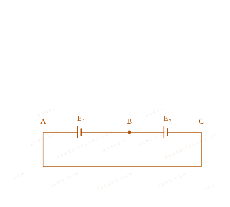
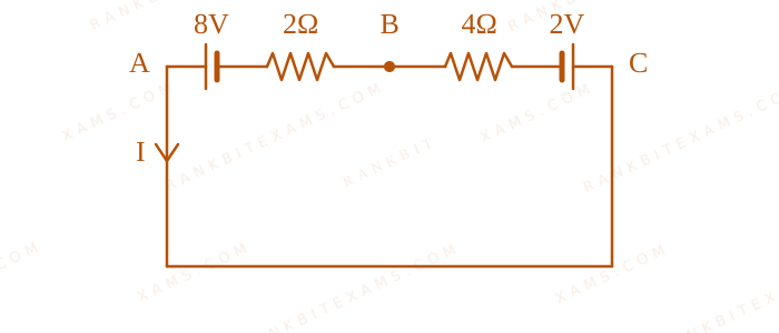
Two cells are connected in opposition as shown. Cell E₁$E_1$ is of 8V$8\mathrm{V}$ emf and 2Ω$2\Omega$ internal resistance; the cell E₂$E_2$ is of 2V$2\mathrm{V}$ emf and 4Ω$4\Omega$ internal resistance. The terminal potential difference of cell E₂$E_2$ is:
Two batteries pushing current against each other.
Numerical Answer.Answer: 6 to 6
Solution
Related Formula
I = EₙₑₜReq$$I = \frac{E_{\text{net}}}{R_{\text{eq}}}$$V = E - Ir (Discharging)$$V = E - Ir \quad (\text{Discharging})$$V = E + Ir (Charging)$$V = E + Ir \quad (\text{Charging})$$
Core Logic
Two batteries pushing current against each other.
Because the cells are in opposition, the net EMF drives current from the higher potential cell (8V$8\mathrm{V}$) to the lower potential cell (2V$2\mathrm{V}$). Thus, the 2V$2\mathrm{V}$ cell acts as a load and undergoes charging.
When a smaller battery is forced backwards by a larger battery, it gets "charged". Consequently, its terminal voltage increases above its nominal EMF: V = E + Ir$V = E + Ir$.
Chapter Mix
Class 12 Physics: Current Electricity
Q33jee_main_2024_30_jan_morningResistors in Series and Voltage Dividers
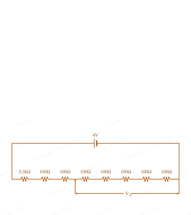
A potential divider circuit is shown in figure. The output voltage V₀$V_0$ is
Circuit containing multiple resistors in series and parallel calculating a specific output voltage.
Observe the circuit diagram. The total equivalent resistance Req$R_{\text{eq}}$ of the series network must be calculated by summing all the resistance values shown in the main branch.
Step 1: Calculate Total Resistance and Current
From the given network, assuming the total series resistance is 4000 Ω$4000 \,\Omega$ (comprising the 3.3kΩ$3.3\mathrm{k}\Omega$ resistor and seven 100 Ω$100\,\Omega$ resistors).
Req = 4000 Ω$$R_{\text{eq}} = 4000 \,\Omega$$
The total voltage applied across the network is 4 ~V$4 \mathrm{~V}$.
A potential divider simply scales the input voltage by the fraction of the resistance tapped over the total resistance: V₀ = Vᵢₙ × (Rₜₐₚ / Rtotal)$V_0 = V_{in} \times (R_{\text{tap}} / R_{\text{total}})$. Standard DC circuit division.
Chapter Mix
Class 12 Physics: Current Electricity
Q43jee_main_2024_30_jan_morningTemperature Dependence of Resistivity
An electric toaster has resistance of 60Ω$60\Omega$ at room temperature (27°C)$(27^{\circ}\mathrm{C})$. The toaster is connected to a 220V$220\mathrm{V}$ supply. If the current flowing through it reaches 2.75A$2.75\mathrm{A}$, the temperature attained by toaster is around: (if α = 2× 10⁻⁴ / °C$\alpha = 2\times 10^{-4} / ^{\circ}\mathrm{C}$)
First, evaluate the final resistance RT$R_T$ at the operating condition using Ohm's law. Second, plug the final resistance into the linear temperature dependence equation for resistance to solve for final temperature T$T$.
Step 1: Calculate Final Resistance
Given V = 220 ~V$V = 220 \mathrm{~V}$ and I = 2.75 ~A$I = 2.75 \mathrm{~A}$:
Always separate the final temperature T$T$ from Δ T$\Delta T$. The most common error is forgetting to add back the initial reference temperature (27^$27^\circ\mathrm{C}$) at the end.
Chapter Mix
Class 12 Physics: Current Electricity
More Current Electricity Questions — jee_main_2025_03_april_morning
Practice past-year questions one chapter at a time. Pick an exam → subject → chapter and get every PYQ for that topic — pulled together from all past papers — with the chapter's key formulas alongside.