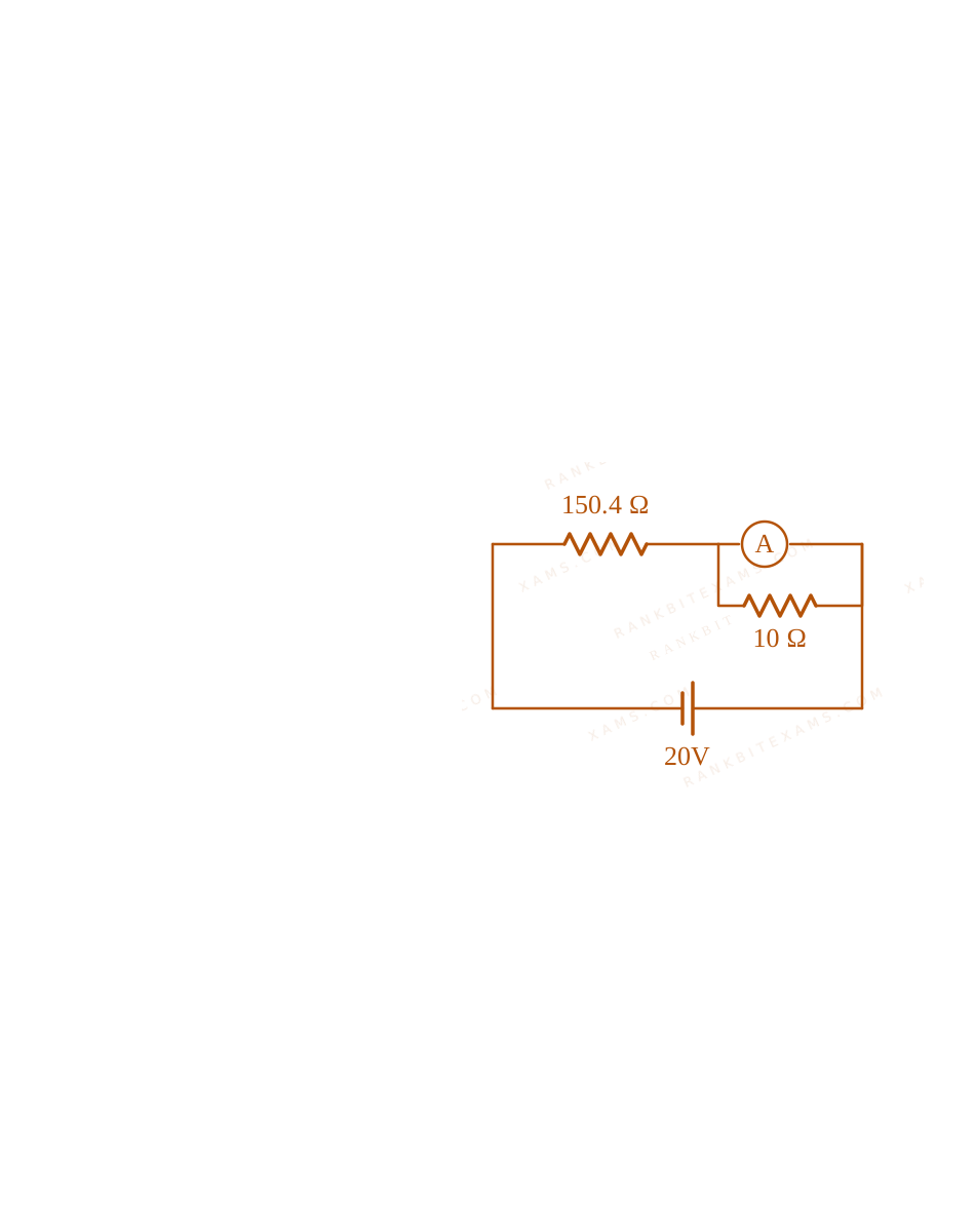
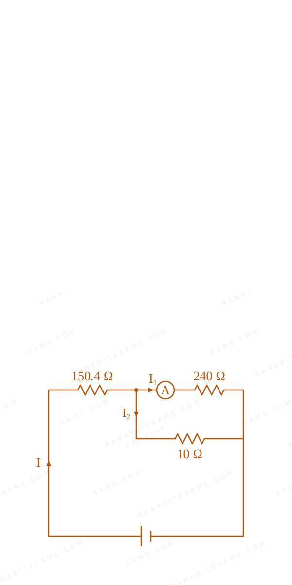
In the figure shown below, a resistance of 150.4Ω$150.4\Omega$ is connected in series to an ammeter A of resistance 240Ω$240\Omega$. A shunt resistance of 10Ω$10\Omega$ is connected in parallel with the ammeter. The reading of the ammeter is ________ mA$\mathrm{mA}$.
A circuit schematic containing a 20V battery connected in series with a 150.4 ohm resistor and a parallel combination of a 240 ohm ammeter and a 10 ohm shunt resistor.
Numerical Answer Type:
Enter a numerical valueAnswer: 5 to 5+4 marks
Solution & Explanation
Related Formula
Parallel combination of ammeter (RG = 240Ω$R_G = 240\Omega$) and shunt (S = 10Ω$S = 10\Omega$):
Therefore, the reading of the ammeter is 5~mA$5\mathrm{~mA}$.
A circuit schematic containing a 20V battery connected in series with a 150.4 ohm resistor and a parallel combination of a 240 ohm ammeter and a 10 ohm shunt resistor.A circuit schematic containing a 20V battery connected in series with a 150.4 ohm resistor and a parallel combination of a 240 ohm ammeter and a 10 ohm shunt resistor.
Pattern Recognition
Notice how nicely the numbers are set up in JEE Mains questions! The parallel combination of 240Ω$240\Omega$ and 10Ω$10\Omega$ yields exactly 9.6Ω$9.6\Omega$, which beautifully combines with 150.4Ω$150.4\Omega$ to form a perfect integer sum of 160Ω$160\Omega$. This tells you that your intermediate steps are absolutely correct!
Chapter Mix
Class 12 Physics: Current Electricity: Measuring Devices
Keywords:#ammeter shunt current divider#galvanometer conversion ammeter#JEE Main 2025 Morning Q25#Ohm's law equivalent resistance#shunted ammeter#current divider rule#equivalent resistance circuit
More Current Electricity Previous-Year Questions — Page 10
Q39jee_main_2024_31_jan_eveningMeter Bridge
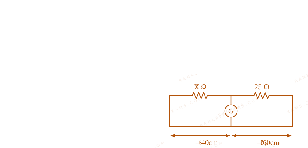
The resistance per centimeter of a meter bridge wire is r$r$, with X Ω$X \, \Omega$ resistance in left gap. Balancing length from left end is at 40 cm$40 \text{ cm}$ with 25 Ω$25 \, \Omega$ resistance in right gap. Now the wire is replaced by another wire of 2r$2r$ resistance per centimeter. The new balancing length for same settings will be at
For a meter bridge, the balancing condition is independent of the absolute resistance of the bridge wire as long as it is uniform. The ratio of the resistances in the gaps balances with the ratio of lengths.
Meter Bridge diagram for Q39 - JEE Main 2024 Evening
Since the ratio X/25$X/25$ remains identical, the balancing length ratio / (100- )$\ell / (100-\ell)$ also remains identical.
Therefore, ₂ = ₁ = 40 cm$\ell_2 = \ell_1 = 40 \text{ cm}$.
Pattern Recognition
Meter bridge balance point strictly depends on length ratio, NOT the specific resistivity or thickness of the wire (provided it is uniform). If external resistors don't change, the balance point never changes.
Chapter Mix
Class 12 Physics: Current Electricity
Q43jee_main_2024_31_jan_eveningPower Dissipation
By what percentage will the illumination of the lamp decrease if the current drops by 20%$20\%$?
A.46%$46\%$
B.26%$26\%$
C.36%$36\%$
D.56%$56\%$
Solution
Related Formula
Power (Illumination) is proportional to the square of the current for a constant resistance:
P = I² R$P = I^2 R$
P₂ = (0.8 I₁)² R = 0.64 I₁² R = 0.64 P₁$$P_2 = (0.8 I_1)^2 R = 0.64 I_1^2 R = 0.64 P_1$$
Step 1: Calculate Percentage Change
Δ P % = (P₂ - P₁)/(P₁) × 100%$$\Delta P \% = \frac{P_2 - P_1}{P_1} \times 100\%$$Δ P % = (0.64 P₁ - P₁)/(P₁) × 100%$$\Delta P \% = \frac{0.64 P_1 - P_1}{P_1} \times 100\%$$Δ P % = (0.64 - 1) × 100% = -36%$$\Delta P \% = (0.64 - 1) \times 100\% = -36\%$$
Step 2: Final Statement
The negative sign indicates a decrease. The illumination drops by 36%$36\%$.
Pattern Recognition
For squared relations y = x²$y = x^2$, if x$x$ changes by a factor k$k$ (0.8$0.8$), y$y$ changes by a factor k²$k^2$ (0.64$0.64$). 1 - 0.64 = 36%$1 - 0.64 = 36\%$. This bypasses algebraic limits usually done for small changes (like 2Δ x / x$2\Delta x / x$) since 20% is too large for approximation.
Chapter Mix
Class 12 Physics: Current Electricity
Q51jee_main_2024_31_jan_eveningPower in DC Circuits
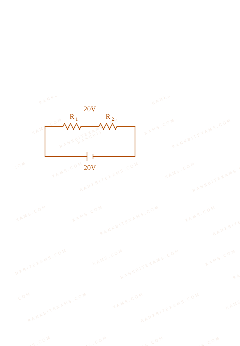
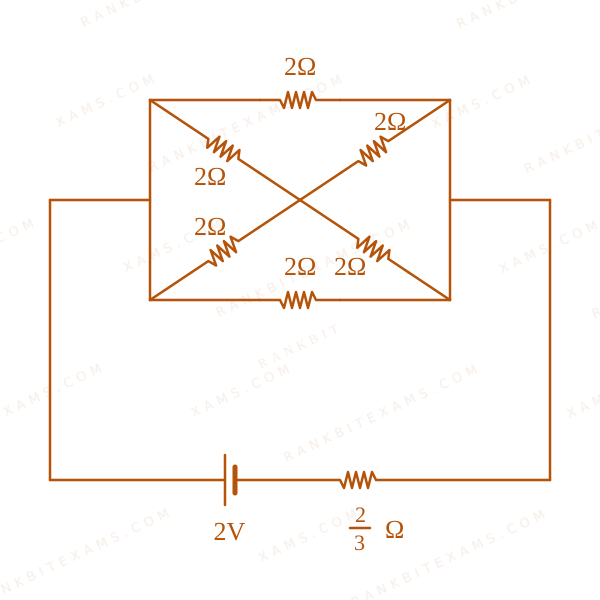
In the following circuit, the battery has an emf of 2 V$2 \text{ V}$ and an internal resistance of (2)/(3) Ω$\frac{2}{3} \, \Omega$. The power consumption in the entire circuit is ______ W.
The image shows a DC circuit with multiple resistors in parallel/series connected to a 2V battery with 2/3 ohm internal resistance.
Numerical Answer.Answer: 3 to 3
Solution
Related Formula
P = V²Req$$P = \frac{V^2}{R_{eq}}$$
Core Logic
To find total power, collapse the entire external circuit and battery internal resistance into a single equivalent resistance Req$R_{eq}$ across the battery's ideal terminals.
Step 1: Equivalent Resistance Calculation
Analyzing the diagram:
The circuit simplifies to an equivalent resistance Req$R_{eq}$ combining the parallel/series elements along with the internal resistance r = 2/3 Ω$r = 2/3 \, \Omega$.
The final simplified equivalent resistance of the entire system calculates to:
Whenever "entire circuit" power is asked, include the battery's internal resistance inside Req$R_{eq}$ so you can use P = E² / Rtotal$P = E^2 / R_{total}$ directly.
Chapter Mix
Class 12 Physics: Current Electricity
Qjee_main_2024_31_jan_morningResistor Circuits
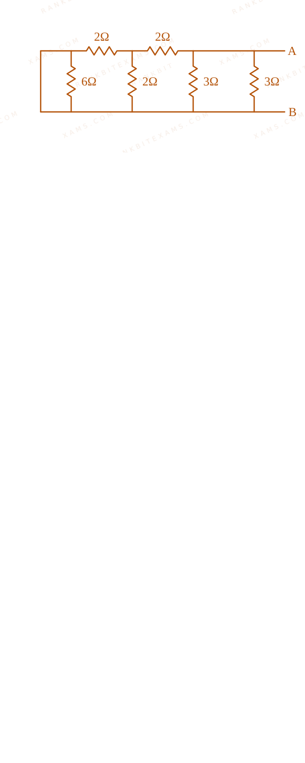
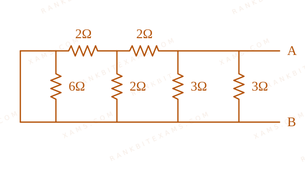
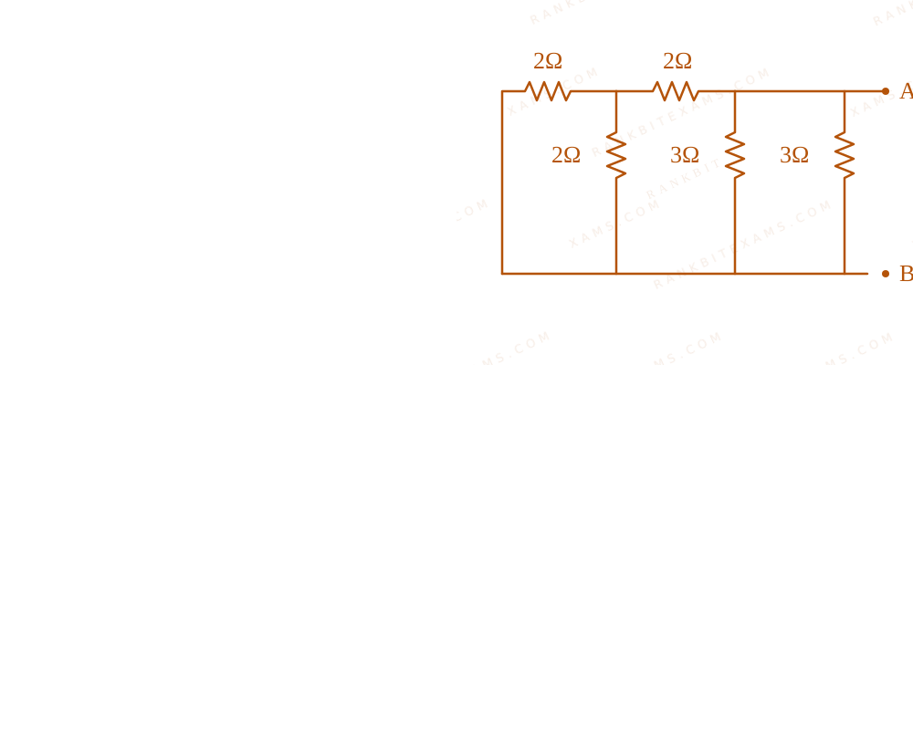
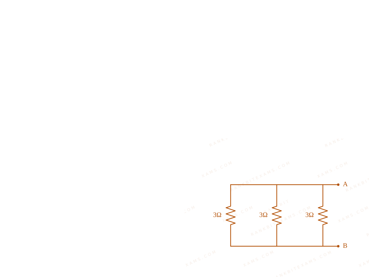
Equivalent resistance of the following network is ________ Ω$\Omega$
A complex resistor bridge network connecting nodes A and B with multiple branches.
A complex resistor bridge network connecting nodes A and B with multiple branches.
By carefully identifying the nodes, we can see that a 6 Ω$6\,\Omega$ resistor in the middle branch is short-circuited by a direct zero-resistance wire path across it.
A complex resistor bridge network connecting nodes A and B with multiple branches.
Removing the short-circuited 6 Ω$6\,\Omega$ resistor simplifies the circuit into three identical branches connected directly between the terminals A$A$ and B$B$.
A complex resistor bridge network connecting nodes A and B with multiple branches.
Step 2: Equivalent Calculation
The simplified circuit consists of three identical 3 Ω$3\,\Omega$ resistors in parallel.
Always trace nodes directly connected by straight wires (zero resistance). Any resistor with both ends connecting to the exact same electrical node is shorted out and can be erased.
Chapter Mix
Class 12 Physics: Current Electricity
Q48jee_main_2024_31_jan_morningTemperature Dependence Of Resistance
Two conductors have the same resistances at 0°C$0^{\circ}\mathrm{C}$ but their temperature coefficients of resistance are α₁$\alpha_1$ and α₂$\alpha_2$. The respective temperature coefficients for their series and parallel combinations are :
1 + αeq,p Δ T ≈ [1 + (α₁ + α₂)Δ T] [ 1 - (α₁ + α₂)/(2)Δ T ]$$1 + \alpha_{\text{eq,p}} \Delta T \approx [1 + (\alpha_1 + \alpha_2)\Delta T] \left[ 1 - \frac{\alpha_1 + \alpha_2}{2}\Delta T \right]$$1 + αeq,p Δ T ≈ 1 + (α₁ + α₂)Δ T - (α₁ + α₂)/(2)Δ T$$1 + \alpha_{\text{eq,p}} \Delta T \approx 1 + (\alpha_1 + \alpha_2)\Delta T - \frac{\alpha_1 + \alpha_2}{2}\Delta T$$αeq,p Δ T = (α₁ + α₂)/(2)Δ T$$\alpha_{\text{eq,p}} \Delta T = \frac{\alpha_1 + \alpha_2}{2}\Delta T$$αeq,p = (α₁ + α₂)/(2)$$\alpha_{\text{eq,p}} = \frac{\alpha_1 + \alpha_2}{2}$$
Pattern Recognition
For two identical base resistances, the effective temperature coefficient is simply the arithmetic mean of their individual coefficients, regardless of whether they are in series or parallel.
Chapter Mix
Class 12 Physics: Current Electricity
More Current Electricity Questions — jee_main_2025_03_april_morning
Practice past-year questions one chapter at a time. Pick an exam → subject → chapter and get every PYQ for that topic — pulled together from all past papers — with the chapter's key formulas alongside.