Two cells of emf 1V and 2V and internal resistance 2Omega$2\Omega$ and 1Omega$1\Omega$, respectively, are connected in series with an external resistance of 6Omega$6\Omega$. The total current in the circuit is I_1$I_{1}$ Now the same two cells in parallel configuration are connected to same external resistance. In this case, the total current drawn is I_2$I_{2}$. The value of (fracI_1I_2)$(\frac{I_{1}}{I_{2}})$ is fracx3$\frac{x}{3}$. The value of x is ________.
Numerical Answer Type:
Enter a numerical valueAnswer: 4 to 4+4 marks
Solution & Explanation
### Related Formula
- Series cell configuration:
varepsilon_texteq = varepsilon_1 + varepsilon_2, quad r_texteq = r_1 + r_2$$\varepsilon_{\text{eq}} = \varepsilon_1 + \varepsilon_2, \quad r_{\text{eq}} = r_1 + r_2$$
- Parallel cell configuration (for unequal cells in parallel):
varepsilon_texteq = fracfracvarepsilon_1r_1 + fracvarepsilon_2r_2frac1r_1 + frac1r_2, quad frac1r_texteq = frac1r_1 + frac1r_2$$\varepsilon_{\text{eq}} = \frac{\frac{\varepsilon_1}{r_1} + \frac{\varepsilon_2}{r_2}}{\frac{1}{r_1} + \frac{1}{r_2}}, \quad \frac{1}{r_{\text{eq}}} = \frac{1}{r_1} + \frac{1}{r_2}$$
- Circuit current:
I = fracvarepsilon_texteqr_texteq + R$$I = \frac{\varepsilon_{\text{eq}}}{r_{\text{eq}} + R}$$
### Core Logic
Given parameters:
- Cell 1: $
### Core Logic
Given parameters:
- Cell 1: $\varepsilon_1 = 1\mathrm{~V}, $, $r_1 = 2\Omega
- Cell 2: $
- Cell 2: $\varepsilon_2 = 2\mathrm{~V}, $, $r_2 = 1\Omega
- External resistance $
- External resistance $R = 6\Omega
### Step 1: Calculate $
### Step 1: Calculate $I_1 (Series Configuration)Grouping of Cells$ (Series Configuration)Grouping of Cells
$varepsilon_texteq = 1 + 2 = 3mathrm~V$\varepsilon_{\text{eq}} = 1 + 2 = 3\mathrm{~V}$$
$r_texteq = 2 + 1 = 3Omega$r_{\text{eq}} = 2 + 1 = 3\Omega$$
$I_1 = frac33 + 6 = frac39 = frac13mathrm~A$I_1 = \frac{3}{3 + 6} = \frac{3}{9} = \frac{1}{3}\mathrm{~A}$
### Step 2: Calculate $I_2$ (Parallel Configuration)Grouping of Cells$$
### Step 2: Calculate $I_2$ (Parallel Configuration)Grouping of Cells
$$\varepsilon_{\text{eq}} = \frac{\frac{1}{2} + \frac{2}{1}}{\frac{1}{2} + \frac{1}{1}} = \frac{0.5 + 2}{1.5} = \frac{2.5}{1.5} = \frac{5}{3}\mathrm{~V}$$
$$r_{\text{eq}} = \frac{r_1 r_2}{r_1 + r_2} = \frac{2 \times 1}{2 + 1} = \frac{2}{3}\Omega$$
$$I_2 = \frac{\varepsilon_{\text{eq}}}{r_{\text{eq}} + R} = \frac{\frac{5}{3}}{\frac{2}{3} + 6} = \frac{\frac{5}{3}}{\frac{20}{3}} = \frac{5}{20} = \frac{1}{4}\mathrm{~A}$
### Step 3: Find ratio and evaluate $x$
$$$
### Step 3: Find ratio and evaluate $x$
$$\frac{I_1}{I_2} = \frac{\frac{1}{3}}{\frac{1}{4}} = \frac{4}{3}$
Comparing with $
Comparing with $\frac{x}{3}:
$:
$x = 4
### Pattern Recognition
For cells connected in parallel, the formula for equivalent EMF $
### Pattern Recognition
For cells connected in parallel, the formula for equivalent EMF $\varepsilon_{\text{eq}}$ can be viewed as a weighted average. Connecting cells in series maximizes EMF but increases internal resistance, while parallel configuration limits EMF to an intermediate value while reducing equivalent internal resistance.
### Evaluation Rubric / Model Answer
null
### Chapter Mix
Class 12 Physics: Current Electricity
More Current Electricity Previous-Year Questions — Page 7
Q51jee_main_2024_31_jan_eveningPower in DC Circuits
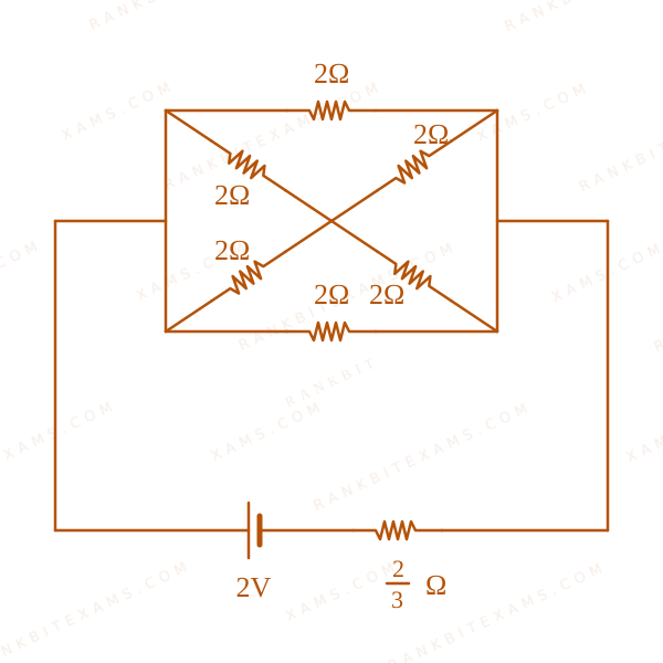
In the following circuit, the battery has an emf of 2 text V$2 \text{ V}$ and an internal resistance of frac23 \, Omega$\frac{2}{3} \, \Omega$. The power consumption in the entire circuit is ______ W.
The image shows a DC circuit with multiple resistors in parallel/series connected to a 2V battery with 2/3 ohm internal resistance.
Numerical Answer.Answer: 3 to 3
Solution
### Related Formula
P = fracV^2R_eq$$P = \frac{V^2}{R_{eq}}$$
### Core Logic
To find total power, collapse the entire external circuit and battery internal resistance into a single equivalent resistance R_eq$R_{eq}$ across the battery's ideal terminals.
### Step 1: Equivalent Resistance Calculation
Analyzing the diagram:
The circuit simplifies to an equivalent resistance R_eq$R_{eq}$ combining the parallel/series elements along with the internal resistance r = 2/3 \, Omega$r = 2/3 \, \Omega$.
The final simplified equivalent resistance of the entire system calculates to:
R_eq = frac43 \, Omega$$R_{eq} = \frac{4}{3} \, \Omega$$
### Step 2: Calculate Power
P = fracV^2R_eq$$P = \frac{V^2}{R_{eq}}$$P = frac2^24/3$$P = \frac{2^2}{4/3}$$P = frac44/3 = 3 text W$$P = \frac{4}{4/3} = 3 \text{ W}$$
### Pattern Recognition
Whenever "entire circuit" power is asked, include the battery's internal resistance inside R_eq$R_{eq}$ so you can use P = E^2 / R_total$P = E^2 / R_{total}$ directly.
### Evaluation Rubric / Model Answer
null
### Chapter Mix
Class 12 Physics: Current Electricity
Q48jee_main_2024_31_jan_morningTemperature Dependence Of Resistance
Two conductors have the same resistances at 0^circmathrmC$0^{\circ}\mathrm{C}$ but their temperature coefficients of resistance are alpha_1$\alpha_1$ and alpha_2$\alpha_2$. The respective temperature coefficients for their series and parallel combinations are :
### Related Formula
R_textparallel = frac1sum frac1R_i$$R_{\text{parallel}} = \frac{1}{\sum \frac{1}{R_i}}$$
### Core Logic
A complex resistor bridge network connecting nodes A and B with multiple branches.
By carefully identifying the nodes, we can see that a 6\,Omega$6\,\Omega$ resistor in the middle branch is short-circuited by a direct zero-resistance wire path across it.
A complex resistor bridge network connecting nodes A and B with multiple branches.
Removing the short-circuited 6\,Omega$6\,\Omega$ resistor simplifies the circuit into three identical branches connected directly between the terminals A$A$ and B$B$.
A complex resistor bridge network connecting nodes A and B with multiple branches.
### Step 2: Equivalent Calculation
The simplified circuit consists of three identical 3\,Omega$3\,\Omega$ resistors in parallel.
R_texteq = 3 times frac13 = 1\,Omega$$R_{\text{eq}} = 3 \times \frac{1}{3} = 1\,\Omega$$
### Pattern Recognition
Always trace nodes directly connected by straight wires (zero resistance). Any resistor with both ends connecting to the exact same electrical node is shorted out and can be erased.
### Evaluation Rubric / Model Answer
null
### Chapter Mix
Class 12 Physics: Current Electricity
More Current Electricity Questions — jee_main_2025_03_april_evening
We Map Every Repeating Question in Competitive Exams.
Say goodbye to generic mock test fatigue. RankBit uses smart analysis to group past exam questions into their foundational Repeating Question Types. Find chapter weightage, track repeating questions, and score higher with targeted practice.
Select Your Target Exam
Choose an exam track below to find formulas per chapter and patterns.
Syncing Exam Intelligence
Mapping formulas and patterns across all tracks…
PATH A — FULL LENGTH PRACTICE
Full Mock Test Hub
Simulate real NTA exam conditions with fully tracked mocks. Time yourself against past papers.
Practice past-year questions one chapter at a time. Pick an exam → subject → chapter and get every PYQ for that topic — pulled together from all past papers — with the chapter's key formulas alongside.
.svg)
.svg)