JEE Main · Physics → Steady

Current Electricity appeared 50 times across 3 years — 5.8% of Physics. This question is from Temperature Dependence Of Resistance.

Year 2026 2025 2024 Total
Questions 18 13 19 50

Two conductors have the same resistances at 0°C but their temperature coefficients of resistance are α₁ and α₂. The respective temperature coefficients for their series and parallel combinations are :

Solution & Explanation

Related Formula
RT = R₀(1 + α Δ T)
Step 1: Series Combination

Let base resistance at 0^° C be R. For series:

Req = R₁ + R₂ (2R)[1 + αeq,s Δ T] = R(1 + α₁ Δ T) + R(1 + α₂ Δ T) 2 + 2αeq,s Δ T = 2 + (α₁ + α₂)Δ T αeq,s = (α₁ + α₂)/(2)
Step 2: Parallel Combination

For parallel at 0^° C, Req,0 = R/2.

Req,p = (R₁ R₂)/(R₁ + R₂) (R)/(2) [1 + αeq,p Δ T] = (R² (1 + α₁ Δ T)(1 + α₂ Δ T))/(R(2 + (α₁ + α₂)Δ T)) (1)/(2) (1 + αeq,p Δ T) = (1 + (α₁ + α₂)Δ T)/(2(1 + (α₁ + α₂)/(2)Δ T))

Using binomial expansion for small Δ T:

1 + αeq,p Δ T ≈ [1 + (α₁ + α₂)Δ T] [ 1 - (α₁ + α₂)/(2)Δ T ] 1 + αeq,p Δ T ≈ 1 + (α₁ + α₂)Δ T - (α₁ + α₂)/(2)Δ T αeq,p Δ T = (α₁ + α₂)/(2)Δ T αeq,p = (α₁ + α₂)/(2)
Pattern Recognition

For two identical base resistances, the effective temperature coefficient is simply the arithmetic mean of their individual coefficients, regardless of whether they are in series or parallel.

Chapter Mix

Class 12 Physics: Current Electricity

Reference Study Guides

More Current Electricity Previous-Year Questions — Page 2

Q36 jee_main_2026_22_january_evening Power Transmission and Efficiency
An electric power line having total resistance of 2 Ω, delivers 1 kW of power of 250 V. The percentage efficiency of transmission line is ____.
  • A. 96.9
  • B. 86.5
  • C. 100
  • D. 92.5

Solution

Related Formula
Pout = V · I Ploss = I² R η = ( PoutPₙₑₜ) × 100%
Core Logic

Calculating total current I:

1000 = 250 × I I = 4 ~A

Calculating power loss along the line Ploss:

Ploss = I² R = (4)² × 2 = 32 ~W

Total input power supplied to line Pₙₑₜ:

Pₙₑₜ = Pout + Ploss = 1000 + 32 = 1032 ~W

Calculating transmission efficiency η:

η = ((1000)/(1032)) × 100% ≈ 96.9%
Step 1: Final Conclusion

The percentage efficiency of the transmission line is 96.9%.

Pattern Recognition

Efficiency formula: η = PoutPout + I² R × 100%. Current I = 1000/250 = 4~A. Loss = 16 × 2 = 32~W. η = 1000/1032 = 96.9%.

Chapter Mix

Class 12 Physics: Current Electricity
Q49 jee_main_2026_22_january_evening Drift Velocity and Electron Mobility
A cylindrical conductor of length 2m and area of cross-section 0.2 ~mm² carries an electric current of 1.6 A when its ends are connected to a 2V battery. Mobility of electrons in the conductor is α × 10⁻³ ~m²/V⋯. The value of α is : (electron concentration = 5 × 10²⁸/m³ and electron charge = 1.6 × 10⁻¹⁹ C)
Numerical Answer. Answer: 1 to 1

Solution

Related Formula

I = n e A vd

vd = μ E = μ (V)/(l) μ = (I l)/(n e A V)
Core Logic

Combining current density and mobility equations:

I = n e A (μ (V)/(l)) μ = (I · l)/(n · e · A · V)

Substituting given values I = 1.6 ~A, l = 2 ~m, n = 5 × 10²⁸ /m³, e = 1.6 × 10⁻¹⁹ ~C, A = 0.2 × 10⁻⁶ ~m², V = 2 ~V:

μ = 1.6 × 2(5 × 10²⁸) × (1.6 × 10⁻¹⁹) × (0.2 × 10⁻⁶) × 2 μ = (3.2)/(1.6 × 10³ × 2) = (3.2)/(3200) = 1.0 × 10⁻³ ~m²/V⋯

Comparing with α × 10⁻³ α = 1.

Step 1: Final Conclusion

The value of α is 1.

Pattern Recognition

Mobility formula: μ = I l / (n e A V). Direct parameter plug-in yields α = 1.

Chapter Mix

Class 12 Physics: Current Electricity
Q34 jee_main_2026_23_january_morning Resistance and Ohm's Law
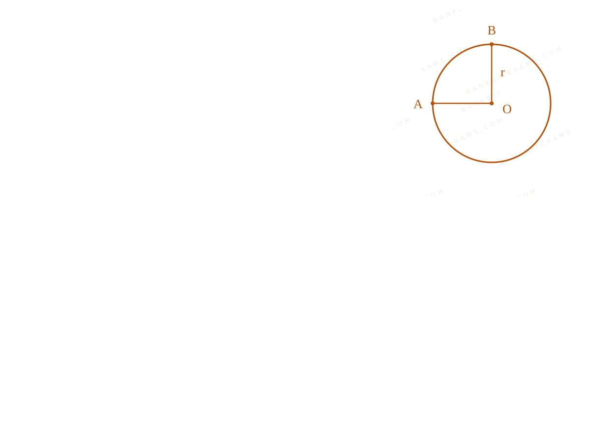
A wire of uniform resistance λΩ/m is bent into a circle of radius r and another piece of wire with length 2r is connected between points A and B (AOB) as shown in figure. The equivalent resistance between points A and B is ____ Ω.
Resistance and Ohm's Law diagram for Q34 - JEE Main 2026 Morning
A ring with nodes A and B connected across a diameter forming parallel branches.
  • A. (3πλ r)/(8)
  • B. (π + 1)2rλ
  • C. (6πλ r)/(3π + 16)
  • D. 2π λ r

Solution

Related Formula

R = ρ L For parallel resistors:

1Req = 1R₁ + 1R₂ + 1R₃
Core Logic

The system represents three resistors connected in parallel between nodes A and B: the upper arc, the lower arc, and the straight diameter wire. Using R = λ L where λ is resistance per unit length.

Step 1: Assign Resistances

Length of the upper arc = (π r)/(2) Resistance R₁ = λ · (π r)/(2)

Length of the straight wire AB = 2r Resistance R₂ = λ · 2r

Length of the remaining larger arc = 2π r - (π r)/(2) = (3π r)/(2) Resistance R₃ = λ · (3π r)/(2)

Step 2: Equivalent Resistance Calculation
1RAB = 1R₁ + 1R₂ + 1R₃ 1RAB = (2)/(λ π r) + (1)/(2λ r) + (2)/(3λ π r) 1RAB = (1)/(λ r)[(2)/(π) + (1)/(2) + (2)/(3π)] 1RAB = (1)/(λ r)((12 + 3π + 4)/(6π)) = (1)/(λ r)((16 + 3π)/(6π))
Step 3: Final Inversion
RAB = λ r ((6π)/(16 + 3π))
Pattern Recognition

Sees: "Uniform resistance wire bent into shape" → immediately break the shape down into parallel/series segments defined purely by their arc/line lengths multiplied by the linear density λ.

Chapter Mix

Class 12 Physics: Current Electricity

Q35 jee_main_2026_23_january_evening Measuring Instruments
To compare EMF of two cells using potentiometer the balancing lengths obtained are 200 cm and 150 cm. The least count of scale is 1 cm. The percentage error in the ratio of EMFs is ____
  • A. 1.45
  • B. 1.65
  • C. 1.75
  • D. 1.55

Solution

Related Formula
ε = λ l (Δ y)/(y) = (Δ l₁)/(l₁) + (Δ l₂)/(l₂)
Core Logic

By potentiometer principle: ε₁ = λ l₁ ε₂ = λ l₂

Ratio y = (ε₁)/(ε₂) = (l₁)/(l₂) Maximum percentage error is the sum of fractional errors.

Step 1: Calculate Percentage Error
(Δ y)/(y) = (1)/(200) + (1)/(150) (Δ y)/(y) = (3 + 4)/(600) = (7)/(600)

Percentage error = (7)/(600) × 100% = (7)/(6)% ≈ 1.16%

Pattern Recognition

Note: The calculated exact percentage error is 1.16%, which does not match any of the provided options exactly. The closest official option provided was tracked as index (2) marking 1.65 by some keys, though technically a bonus question.

Chapter Mix

Class 12 Physics: Current Electricity Class 11 Physics: Units and Measurements

Q30 jee_main_2026_24_january_morning Measuring Instruments
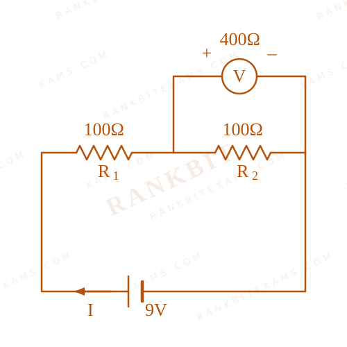
Two resistors of 100 Ω each are connected in series with a 9V battery. A voltmeter of 400Ω resistance is connected to measure the voltage drop across one of the resistors. The voltmeter reading is ____ V.
  • A. 3
  • B. 4.5
  • C. 4
  • D. 2

Solution

Related Formula
Req(parallel) = (R₁ R₂)/(R₁ + R₂)

V = I · R

Core Logic

Circuit diagram with voltmeter in parallel

The voltmeter is connected in parallel with one of the 100 Ω resistors. The equivalent resistance of this parallel combination is:

Rparallel = (400 × 100)/(400 + 100) = (40000)/(500) = 80 Ω

The total equivalent resistance of the circuit is:

Req = 100 + 80 = 180 Ω
Step 1: Circuit Current and Voltmeter Reading

Current in the circuit:

I = EReq = (9)/(180) = (1)/(20) A

The reading of the voltmeter is the voltage across the parallel combination:

V = I × 80 = (1)/(20) × 80 = 4 V
Pattern Recognition

When a real voltmeter is used, it draws current. Model it as a resistor in parallel with the test component to find the exact altered potential drop.

Chapter Mix

Class 12 Physics: Current Electricity

More Current Electricity Questions — jee_main_2024_31_jan_morning

Practice all Current Electricity previous-year questions →

Rankbit System
JEE Physics: Waves (+15.5%) | Electrostatics: Concentric Shells (-29.7%) | Modern Physics: Photoelectric Clones (+34.2%) | Mathematics: Definite Integrals (+18.1%) | Chemistry: Coordination Splitting (-11.4%) | JEE Physics: Waves (+15.5%) | Electrostatics: Concentric Shells (-29.7%) | Modern Physics: Photoelectric Clones (+34.2%) | Mathematics: Definite Integrals (+18.1%) | Chemistry: Coordination Splitting (-11.4%)