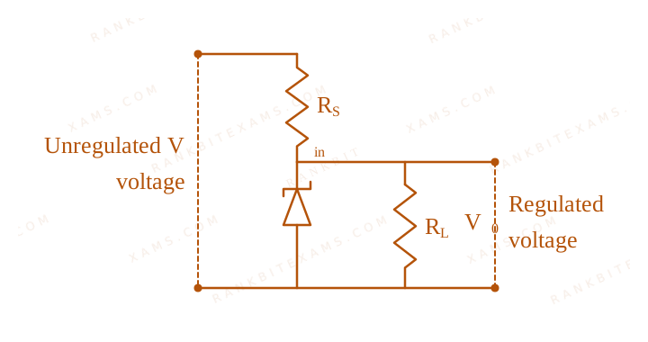
The following diagram shows a Zener diode as a voltage regulator. The Zener diode is rated at VZ = 5V and the desired current in load is 5 mA. The unregulated voltage source can supply up to 25V. Considering the Zener diode can withstand four times of the load current, the value of resistor RS (shown in circuit) should be ____ Ω.
Zener Diode diagram for Q37 - JEE Main 2026 Morning
Circuit containing unregulated voltage, series resistor Rs, Zener diode, and load resistor.

Solution & Explanation

Related Formula
Itotal = IZ + IL Vᵢₙ - VZ = Itotal RS
Core Logic

The question is dropped by the examination authority, meaning there was an anomaly in data or multiple correct interpretations, likely due to imprecise wording regarding the maximum source voltage and the exact safe current rating. In a nominal calculation, I_Zmax = 4 × 5 mA = 20 mA. Total current I = 25 mA. RS = (25 - 5) / (25 × 10⁻³) = 800Ω, which is not in the options.

Step 1: Final Conclusion

Question Dropped.

Pattern Recognition

Sees: "Question Dropped" → This often occurs when mathematical data maps to none of the provided MCQs.

Chapter Mix

Class 12 Physics: Semiconductor Electronics: Materials, Devices and Simple Circuits
Reference Study Guides

More Semiconductor Electronics: Materials, Devices and Simple Circuits Previous-Year Questions — Page 4

Q jee_main_2025_28_jan_morning Logic Gates
Which of the following circuits has the same output as that of the given circuit?
Logic Gates diagram for Q13 - JEE Main 2025 Morning
A combination gate circuit configuration evaluated for total Boolean output expressions.
  • A.
  • B.
  • C.
  • D.

Solution

Core Logic

Let's perform Boolean analysis on the configuration steps mapped below:

P = A · B Q = A · B Y = P + Q = A · B + A · B

Factoring using distributive Boolean rules:

Y = A · (B + B) = A · 1 Y = A
Step 1: Final Reduction

The expression reduces to a simple inverter (NOT gate) processing input A. This aligns with Circuit (1), matching option (1).

Pattern Recognition

Identify standard combinations: (A AND NOT B) OR (A AND B) collapses back into simply input A because operand B covers all possible states.

Chapter Mix

Class 12 Physics: Semiconductor Electronics: Materials, Devices and Simple Circuits

Q jee_main_2025_03_april_morning Logic Gates
Choose the correct logic circuit for the given truth table having inputs A and B.
InputsOutput
ABY
000
010
101
111
  • A.
  • B.
  • C.
  • D.

Solution

Related Formula

Let us inspect the Boolean expression for the output Y from the truth table. From the table:

  • If A=0, Y=0 regardless of B.
  • If A=1, Y=1 regardless of B.
  • Thus, the truth table is represented by the simple direct logical equation: Y = A

Core Logic

Let's check the Boolean output of the options shown in the question paper:

  • Circuit (1): Inputs A and B go into an OR gate, outputting (A + B). This output and B then go to an AND gate.
Y = (A + B) · B = A· B + B· B = B(A + 1) = B

This gives Y = B (Not matching table).

  • Circuit (2): Inputs A and B go into an OR gate, outputting (A + B). This and A then go into an AND gate.
Y = (A + B) · A = A· A + A· B = A + A· B = A(1 + B) = A

This gives Y = A (Perfect match to the truth table where Y exactly copies A).

Step 1: Verification of Circuit (2)

Let's double-check the truth table values for Circuit (2):

  • For A=0, B=0: Y = (0 + 0) · 0 = 0.
  • For A=0, B=1: Y = (0 + 1) · 0 = 0.
  • For A=1, B=0: Y = (1 + 0) · 1 = 1.
  • For A=1, B=1: Y = (1 + 1) · 1 = 1.
  • This perfectly matches the given truth table. Therefore, Circuit (2) is correct.

Pattern Recognition

Identify the logic expression directly from the truth table first! Notice that Y is completely independent of B and strictly equals A. This immediately points to any Boolean simplification that collapses to A (such as absorption law: A(A+B) = A).

Chapter Mix

Class 12 Physics: Semiconductor Electronics: Materials, Devices and Simple Circuits

Q16 jee_main_2025_04_april_evening Extrinsic Semiconductors
Consider a n-type semiconductor in which nₑ and nh are number of electrons and holes, respectively. (A) Holes are minority carriers (B) The dopant is a pentavalent atom (C) nₑnh≠ nᵢ² (where nᵢ is number of electrons or holes in semiconductor when it is in intrinsic form) (D) nₑnh≥ nᵢ² (E) The holes are not generated due to the donors Choose the correct answer from the options given below:
  • A. (A), (C), (D) only
  • B. (A), (C), (E) only
  • C. (A), (B), (E) only
  • D. (A), (B), (C) only

Solution

Related Formula

Mass Action Law:

nₑ · nh = nᵢ²
Core Logic

Let's analyze each statement for an n-type semiconductor:

  • (A) Holes are minority carriers: True, electrons are the majority carriers.
  • (B) The dopant is a pentavalent atom: True (like Phosphorus, Arsenic) which provides extra free electrons.
  • (C) and (D) contradict the fundamental mass action law nₑ nh = nᵢ², so they are False.
  • (E) Holes are generated purely due to thermal excitation, not due to donor atoms: True.
Step 1: Assemble Correct Set

Statements (A), (B), and (E) are explicitly correct.

Pattern Recognition

Mass action law (nₑ nh = nᵢ²) holds uniformly for both doped types at thermal equilibrium. In n-type systems, donors directly inject electrons only; holes emerge solely from thermal breakages of lattice bonds.

Chapter Mix

Class 12 Physics: Semiconductor Electronics

Q jee_main_2025_04_april_morning Logic Gates
The Boolean expression Y=AoverlineBC+overlineAoverlineC can be realised with which of the following gate configurations. A. One 3-input AND gate, 3 NOT gates and one 2-input OR gate, One 2-input AND gate B. One 3-input AND gate, 1 NOT gate, One 2-input NOR gate and one 2-input OR gate C. 3-input OR gate, 3 NOT gates and one 2-input AND gate Choose the correct answer from the options given below
  • A. B, C Only
  • B. A, B Only
  • C. A, B, C Only
  • D. A, C Only

Solution

Related Formula

Given logical expression:

Y = A BC + A C

By De Morgan's laws:

A· C = A+C (NOR configuration)
Core Logic

Let's analyze configurations A and B:

  • Configuration A: Generates A BC using one 3-input AND gate and one NOT gate for input B. Generates A C using one 2-input AND gate and two separate NOT gates for inputs A and C. Combines both terms using a 2-input OR gate.
  • (Total: one 3-input AND, one 2-input AND, three NOT gates, one 2-input OR gate).

    Logic circuit layout A for Q15 - JEE Main 2025 Morning
    Logic circuit layout A for Q15 - JEE Main 2025 Morning

Step 1: Verify Configuration B
  • Configuration B: Generates A BC using one 3-input AND gate and one NOT gate for input B. Simplifies the second term A C into A+C, realized directly with a single 2-input NOR gate. Combines both sub-circuits using a 2-input OR gate.
  • (Total: one 3-input AND, one 2-input NOR, one NOT gate, one 2-input OR gate).

    Logic circuit layout A for Q15 - JEE Main 2025 Morning
    Logic circuit layout A for Q15 - JEE Main 2025 Morning

Step 2: Verify Configuration C
  • Configuration C: Specifies a 3-input OR gate and a 2-input AND gate at the output, which implements a product-of-sums form rather than the required sum-of-products expression. Hence, Configuration C is invalid.
  • Both configurations A and B correctly realize the logic function.

Pattern Recognition

Apply De Morgan's theorem (A· B = A+B) to convert negated AND products into standard NOR gate structures, reducing the total gate count.

Evaluation Rubric / Model Answer

Option B: A, B Only

Chapter Mix

Class 12 Physics: Semiconductor Electronics

Q11 jee_main_2025_07_april_evening Logic Gates
Consider the following logic circuit.
Logic Gates diagram for Q11 - JEE Main 2025 Evening
The diagram illustrates a combination of an AND gate, an inverter, an OR gate, and a terminal NAND gate with inputs A and B.
The output is Y=0 when : [cite: 64, 89]
  • A. A=1 and B=1 [cite: 90]
  • B. A=0 and B=1 [cite: 99]
  • C. A=1 and B=0 [cite: 91]
  • D. A=0 and B=0 [cite: 100]

Solution

Core Logic

Let the intermediate outputs of the first layers be Y₁ and Y₂ [cite: 747]:

  • Top gate is an AND gate with inputs A and B, so Y₁ = A · B [cite: 747].
  • Bottom gate is an OR gate where one input is B and the other is A via a NOT gate, so Y₂ = A + B [cite: 747].
  • The final layer is a NAND gate with inputs Y₁ and Y₂, so Y = Y₁ · Y₂[cite: 748].
Step 1: Constructing the Truth Table

Let's compute the output Y for all binary input pairs (A, B) [cite: 757]:

  • For A=0, B=0 Y₁ = 0, Y₂ = 1 Y = 0 · 1 = 1 [cite: 757].
  • For A=1, B=0 Y₁ = 0, Y₂ = 0 Y = 0 · 0 = 1 [cite: 757].
  • For A=0, B=1 Y₁ = 0, Y₂ = 1 Y = 0 · 1 = 1 [cite: 757].
  • For A=1, B=1 Y₁ = 1, Y₂ = 1 Y = 1 · 1 = 0 [cite: 757].
  • Thus, Y=0 uniquely when A=1 and B=1[cite: 89, 90, 757].

Pattern Recognition

A NAND gate produces an output of 0 if and only if all its inputs are 1. Working backward, this instantly sets Y₁=1 and Y₂=1. For Y₁ = A · B = 1, we must have A=1 and B=1 simultaneously.

Chapter Mix

Class 12 Physics: Semiconductors

More Semiconductor Electronics: Materials, Devices and Simple Circuits Questions — jee_main_2026_23_january_morning

Practice all Semiconductor Electronics: Materials, Devices and Simple Circuits previous-year questions →

Rankbit System
JEE Physics: Waves (+15.5%) | Electrostatics: Concentric Shells (-29.7%) | Modern Physics: Photoelectric Clones (+34.2%) | Mathematics: Definite Integrals (+18.1%) | Chemistry: Coordination Splitting (-11.4%) | JEE Physics: Waves (+15.5%) | Electrostatics: Concentric Shells (-29.7%) | Modern Physics: Photoelectric Clones (+34.2%) | Mathematics: Definite Integrals (+18.1%) | Chemistry: Coordination Splitting (-11.4%)