JEE Main · Physics ↑ Rising

Electromagnetic Induction appeared 28 times across 3 years — 3.2% of Physics. This question is from Motional Electromotive Force.

Year 2026 2025 2024 Total
Questions 12 6 10 28

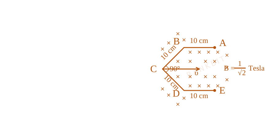
Conductor wire ABCDE with each arm 10~cm in length is placed in magnetic field of 1√(2)~Tesla, perpendicular to its plane. When conductor is pulled towards right with constant velocity of 10~cm/s, induced emf between points A and E is ________ mV.
Conductor wire path geometry layout for Q25 - JEE Main 2025 Morning
The figure outlines a segmented conductive wire trail pulled laterally through an orthogonal inward magnetic field matrix region.

Numerical Answer Type:
Enter a numerical value Answer: 10 to 10 +4 marks

Solution & Explanation

Related Formula

Motional electromotive force formula:

ε = B v leff

where leff is the perpendicular component of the straight-line displacement vector connecting the endpoints A and E (lAE) relative to velocity v.

Core Logic

In a uniform magnetic field, the motional EMF induced in any arbitrary conductor wire depends solely on the straight-line displacement vector connecting its endpoints, rather than the detailed path:

ε = ( v × B) · leff

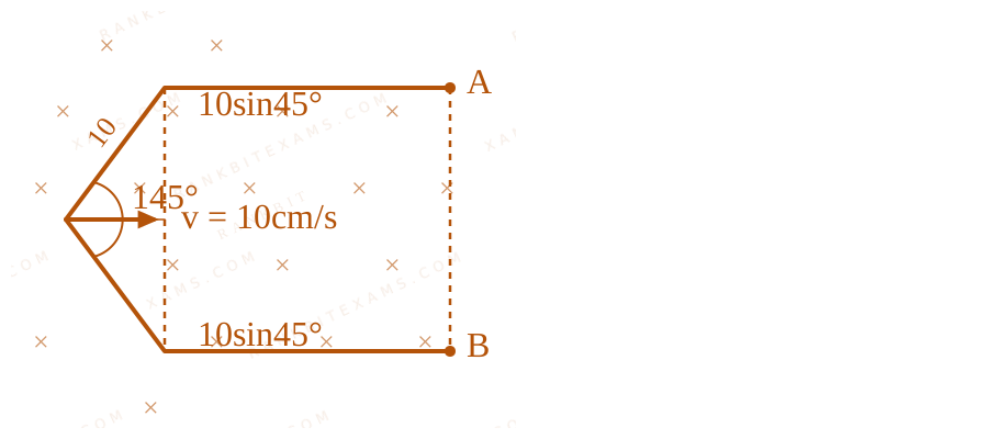
Effective vector length translation resolution mapping for Q25 - JEE Main 2025 Morning
The figure outlines a segmented conductive wire trail pulled laterally through an orthogonal inward magnetic field matrix region.

Step 1: Compute Effective Length

From the geometry of the symmetric wire segments oriented at 45° to the horizontal:

leff = 2 × (10 45°) = 2 × 10 × 1√(2) = 10√(2) cm = 0.1√(2) m
Step 2: Calculate Induced EMF

Substitute the given parameters into the motional EMF expression:

ε = B v leff ε = ( 1√(2)) × (0.1 m/s) × (0.1√(2) m) ε = 1√(2) × 0.1 × 0.1√(2) = 0.01 V = 10 mV
Pattern Recognition

In a uniform magnetic field, motional EMF is path-independent. Replace any zig-zag or curved conductor with an equivalent straight line joining the two endpoints perpendicular to the velocity vector.

Evaluation Rubric / Model Answer

10

Chapter Mix

Class 12 Physics: Electromagnetic Induction

More Electromagnetic Induction Previous-Year Questions — Page 4

Q21 jee_main_2025_28_jan_evening Motional EMF
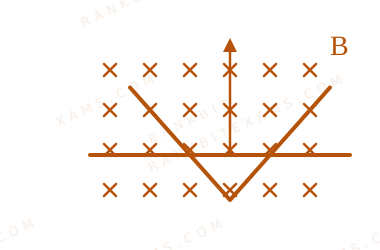
A conducting \bar moves on two conducting rails as shown in the figure. A constant magnetic field B \exists into the page. The \bar starts to move from the vertex at time t = 0 with a constant velocity. If the induced EMF is E ∝ tⁿ , then value of n is
Motional EMF diagram for Q21 - JEE Main 2025 Evening
A linear conductor \bar moving laterally across V-shaped intersecting conducting guide rails.
Numerical Answer. Answer: 1

Solution

Related Formula

The motional EMF induced across a moving conductor of instantaneous length inside a perpendicular uniform magnetic field is given by:

E = B · · v
Core Logic

Let the V-shaped guide rails form an \angle, so that the instantaneous length of the conducting \bar grows linearly with its horizontal position distance x from the vertex [cite: 782, 791]:

∝ x

Since the \bar moves with a constant velocity v, its displacement position at any time t is :

x = v · t ∝ v · t

Substituting this time-dependent length into the induced EMF expression :

E = B · · v E ∝ B · (v · t) · v E ∝ t¹

Comparing this to the given relation E ∝ tⁿ gives the exponent[cite: 188, 791]:

n = 1

Step 1: Geometric Analysis

The expanding circuit loop configuration across time is shown below:
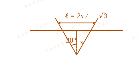
Motional EMF geometric analysis diagram for Q21
A linear conductor \bar moving laterally across V-shaped intersecting conducting guide rails.

Pattern Recognition

For \parallel rails, the length remains constant, meaning induced EMF is independent of time (E ∝ t⁰). For V-shaped divergent rails, the effective length increases linearly with distance, making the induced EMF directly proportional to time (E ∝ t¹).

Chapter Mix

Class 12 Physics: Electromagnetic Induction
Q jee_main_2025_29_jan_morning Mutual Inductance
Consider I₁ and I₂ are the currents flowing simultaneously in two nearby coils 1 & 2, respectively. If L₁ = self inductance of coil 1, M₁₂ = mutual inductance of coil 1 with respect to coil 2, then the value of induced emf in coil 1 will be
  • A. ε₁ = -L₁ dI₁dt +M₁₂ dI₂dt
  • B. ε₁ = -L₁ dI₁dt -M₁₂ dI₁dt
  • C. ε₁ = -L₁ dI₁dt -M₁₂ dI₂dt
  • D. ε₁ = -L₁ dI₂dt -M₁₂ dI₁dt

Solution

Related Formula
φ₁ = L₁ I₁ + M₁₂ I₂ ε₁ = - dφ₁dt
Core Logic

The total flux linked with coil 1 is due to its own current I₁ and the mutual influence of current I₂ in the neighboring coil :

φ₁ = L₁ I₁ + M₁₂ I₂

Differentiating with respect to time according to Faraday\'s Law yields :

ε₁ = -L₁ dI₁dt - M₁₂ dI₂dt
Pattern Recognition

Total induced emf sums both self-induction and mutual induction effects additively with standard Lenz law negative signs.

Chapter Mix

Class 12 Physics: Electromagnetic Induction

Q jee_main_2025_29_jan_morning AC Generator
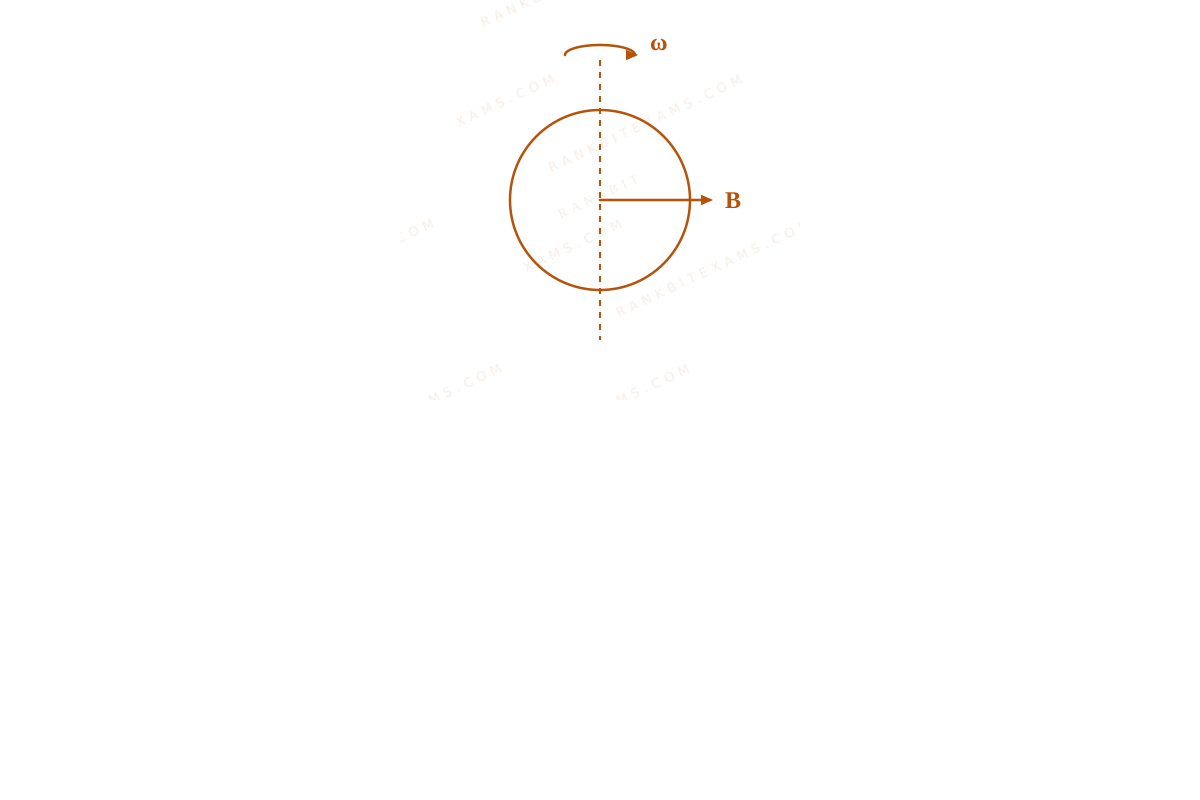
A coil of area A and N turns is rotating with angular velocity ω in a uniform magnetic field B about an axis perpendicular to B . Magnetic flux φ and induced emf ε across it, at an instant when B is parallel to the plane of coil, are:
  • A. φ = AB,ε = 0
  • B. φ = 0, ε = NABω
  • C. φ = 0, ε = 0
  • D. φ = AB,ε = NABω

Solution

Related Formula
φ = BAN (ω t) ε = BANω (ω t)
Core Logic

AC Generator explanation diagram for Q12

When the magnetic field vector B lines up parallel to the plane of the coil, the norm area vector stands perpendicular to B, yielding ω t = (π)/(2). Thus :

φ = BAN ((π)/(2)) = 0 ε = BANω ((π)/(2)) = NABω
Pattern Recognition

Flux is zero when the field lines are parallel to the coil surface, but the rate of change of flux (and thus emf) peaks to its absolute maximum.

Chapter Mix

Class 12 Physics: Electromagnetic Induction

Q jee_main_2024_01_february_morning Induced EMF
A rectangular loop of sides 12~cm and 5~cm, with its sides parallel to the x-axis and y-axis respectively moves with a velocity of 5~cm/s in the positive x-axis direction, in a space containing a variable magnetic field in the positive z-direction. The field has a gradient of 10⁻³~T/cm along the negative x-direction and it is decreasing with time at the rate of 10⁻³~T/s. If the resistance of the loop is 6~mΩ, the power dissipated by the loop as heat is x × 10⁻⁹~W. The value of x is:
Numerical Answer. Answer: 216 to 216

Solution

Related Formula

Total induced EMF in a moving loop within a time-varying spatial field:

εₙₑₜ = εmotional + εtime εmotional = l · v · Δ B = l · v · ((dB)/(dx) · Δ x) εtime = A · (dB)/(dt)
Core Logic

Loop dimensions: l = 5~cm = 0.05~m, Δ x = 12~cm = 0.12~m. Velocity v = 5~cm/s = 0.05~m/s. Spatial gradient (dB)/(dx) = 10⁻³~T/cm = 0.1~T/m. Time decay rate (dB)/(dt) = 10⁻³~T/s.

Calculate the motional component across the leading edges:

εmotional = 300 × 10⁻⁷~V

Calculate the time-varying field induction across the loop area:

A = 12 × 5 = 60~cm² = 60 × 10⁻⁴~m² εtime = A · (dB)/(dt) = 60 × 10⁻⁴ × 10⁻³ = 60 × 10⁻⁷~V

Both changes induce current in the same direction according to Lenz's law:

εₙₑₜ = 300 × 10⁻⁷ + 60 × 10⁻⁷ = 360 × 10⁻⁷~V
Step 1: Calculate Dissipated Power

Given loop resistance R = 6~mΩ = 6 × 10⁻³~Ω:

P = εₙₑₜ²R = (360 × 10⁻⁷)²6 × 10⁻³ = 129600 × 10⁻¹⁴6 × 10⁻³ P = 21600 × 10⁻¹¹ = 216 × 10⁻⁹~W

Therefore, x = 216.

Pattern Recognition

When a loop moves through a field that changes in both space and time, the total induced EMF is the sum of the motional EMF (v(∂ B)/(∂ x)) and the transformer EMF (A(∂ B)/(∂ t)).

Chapter Mix

Class 12 Physics: Electromagnetic Induction

Q52 jee_main_2024_29_january_evening Motional Electromotive Force
A horizontal straight wire 5 m long extending from east to west falling freely at right angle to horizontal component of earth's magnetic field 0.60 × 10⁻⁴ Wb m⁻². The instantaneous value of emf induced in the wire when its velocity is 10 ms⁻¹ is x × 10⁻³ V. The value of x is:
Numerical Answer. Answer: 3 to 3

Solution

Related Formula

The motional electromotive force (emf) induced in a conductor of length L moving with velocity v perpendicular to a magnetic field B is:

e = B v L

Core Logic

Given parameters:

  • Length of wire, L = 5 m
  • Horizontal magnetic field component, BH = 0.60 × 10⁻⁴ Wb m⁻²
  • Velocity of fall, v = 10 ms⁻¹
Step 1: Calculate the Induced EMF

Substitute the parameters directly into the motional emf formula:

e = BH v L

e = (0.60 × 10⁻⁴ Wb m⁻²) × (10 ms⁻¹) × (5 m) e = 3 × 10⁻³ V

Comparing this to x × 10⁻³ V, we find:

x = 3

Pattern Recognition

Motional EMF is directly the product of field, velocity, and length (e = B v L) when they are mutually perpendicular. A simple multiplication is all that is required here.

Chapter Mix

Class 12 Physics: Electromagnetic Induction

More Electromagnetic Induction Questions — jee_main_2025_04_april_morning

Practice all Electromagnetic Induction previous-year questions →

Rankbit System
JEE Physics: Waves (+15.5%) | Electrostatics: Concentric Shells (-29.7%) | Modern Physics: Photoelectric Clones (+34.2%) | Mathematics: Definite Integrals (+18.1%) | Chemistry: Coordination Splitting (-11.4%) | JEE Physics: Waves (+15.5%) | Electrostatics: Concentric Shells (-29.7%) | Modern Physics: Photoelectric Clones (+34.2%) | Mathematics: Definite Integrals (+18.1%) | Chemistry: Coordination Splitting (-11.4%)