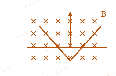
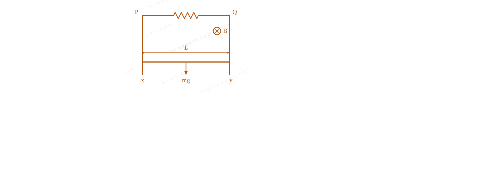
A conducting \bar moves on two conducting rails as shown in the figure. A constant magnetic field B \exists into the page. The \bar starts to move from the vertex at time t = 0$t = 0$ with a constant velocity. If the induced EMF is E ∝ tⁿ$E \propto t^n$ , then value of n$n$ is
A linear conductor \bar moving laterally across V-shaped intersecting conducting guide rails.
Numerical Answer Type:
Enter a numerical valueAnswer: 1+4 marks
Solution & Explanation
Related Formula
The motional EMF induced across a moving conductor of instantaneous length $\ell$ inside a perpendicular uniform magnetic field is given by:
E = B · · v$$E = B \cdot \ell \cdot v$$
Core Logic
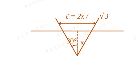
Let the V-shaped guide rails form an \angle, so that the instantaneous length $\ell$ of the conducting \bar grows linearly with its horizontal position distance x$x$ from the vertex [cite: 782, 791]:
∝ x$\ell \propto x$
Since the \bar moves with a constant velocity v$v$, its displacement position at any time t$t$ is :
x = v · t ∝ v · t$$x = v \cdot t \implies \ell \propto v \cdot t$$
Substituting this time-dependent length into the induced EMF expression :
E = B · · v E ∝ B · (v · t) · v E ∝ t¹$$E = B \cdot \ell \cdot v \implies E \propto B \cdot (v \cdot t) \cdot v \implies E \propto t^1$$
Comparing this to the given relation E ∝ tⁿ$E \propto t^n$ gives the exponent[cite: 188, 791]:
n = 1$n = 1$
Step 1: Geometric Analysis
The expanding circuit loop configuration across time is shown below:
A linear conductor \bar moving laterally across V-shaped intersecting conducting guide rails.
Pattern Recognition
For \parallel rails, the length $\ell$ remains constant, meaning induced EMF is independent of time (E ∝ t⁰$E \propto t^0$). For V-shaped divergent rails, the effective length increases linearly with distance, making the induced EMF directly proportional to time (E ∝ t¹$E \propto t^1$).
Keywords:#induced emf on v-shaped conducting rails#JEE Main 2025 Evening Q21#Electromagnetic Induction JEE Main 2025#motional induction time exponent#motional emf#conducting rails#time dependent induction
More Electromagnetic Induction Previous-Year Questions
Qjee_main_2026_21_jan_morningMotional EMF
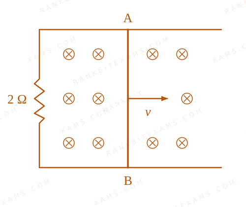
A 1 m long metal rod AB completes the circuit as shown in figure. The area of circuit is perpendicular to the magnetic field of 0.10 T. If the resistance of the total circuit is 2Ω$2\Omega$ then the force needed to move the rod towards right with constant speed (v) of 1.5 m/s is ____ N.
A conducting rod AB moves on a U-shaped rail in a perpendicular magnetic field.
A.7.5 × 10⁻²$7.5 \times 10^{-2}$
B.5.7 × 10⁻³$5.7 \times 10^{-3}$
C.5.7 × 10⁻²$5.7 \times 10^{-2}$
D.7.5 × 10⁻³$7.5 \times 10^{-3}$
Solution
Related Formula
E = B l v$E = B l v$
i = (E)/(R)$$i = \frac{E}{R}$$FB = i l B = (B² l² v)/(R)$$F_{B} = i l B = \frac{B^2 l^2 v}{R}$$
Core Logic
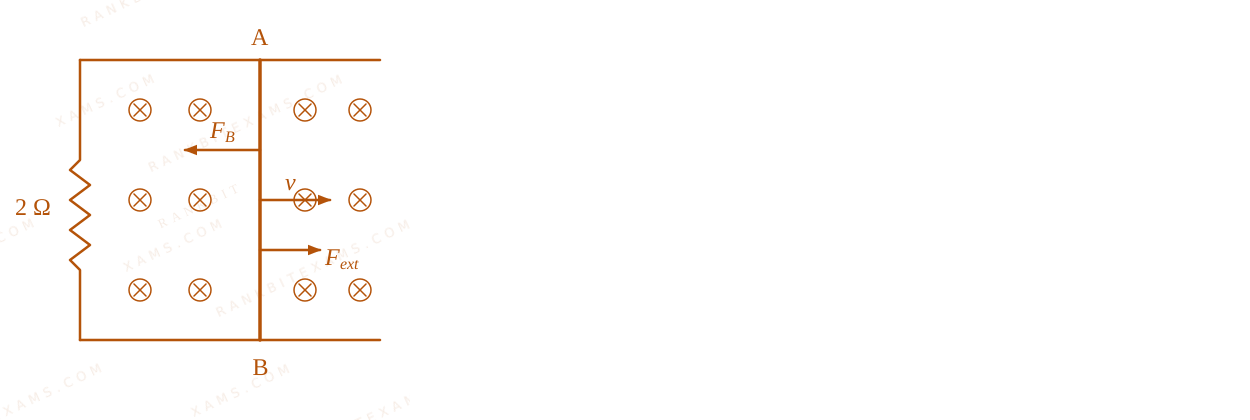
To maintain a constant speed, the external force applied must balance the opposing magnetic force generated by the induced current.
A conducting rod AB moves on a U-shaped rail in a perpendicular magnetic field.
Pattern Recognition
Standard "sliding rod on rails" problem. The required mechanical force to maintain terminal velocity is always F = (B² L² v)/(R)$F = \frac{B^2 L^2 v}{R}$.
Chapter Mix
Class 12 Physics: Electromagnetic Induction
Q28jee_main_2026_21_jan_morningFaraday's Law
A conducting circular loop of area1.0 m²$1.0 \, \mathrm{m}^{2}$ is placed perpendicular to a magnetic field which varies as B = (100 t) Tesla$B = \sin(100 \, t)\text{ Tesla}$. If the resistance of the loop is 100 Ω$100 \, \Omega$, then the average thermal energy dissipated in the loop in one period is ____ J.
A.(π)/(2)$\frac{\pi}{2}$
B.2π$2\pi$
C.π$\pi$
D.π²$\pi^{2}$
Solution
Related Formula
φ = B · A$$\phi = B \cdot A$$E = -(dφ)/(dt)$$E = -\frac{d\phi}{dt}$$P = (E²)/(R)$$P = \frac{E^2}{R}$$
Core Logic
Given area of the loop, A = 1 m²$A = 1\text{ m}^2$ and magnetic field B = (100t)$B = \sin(100t)$.
The magnetic flux passing through the loop is:
φ = B · A = (100t) × 1 = (100t)$$\phi = B \cdot A = \sin(100t) \times 1 = \sin(100t)$$
Instantaneous power P = (E²)/(R) = (100² ²(100t))/(100) = 100 ²(100t)$P = \frac{E^2}{R} = \frac{100^2 \cos^2(100t)}{100} = 100\cos^2(100t)$.
Thermal energy dissipated in one time period T$T$:
Q = ∫₀T P dt = ∫₀T 100 ²(100t) dt$$Q = \int_{0}^{T} P \, dt = \int_{0}^{T} 100\cos^2(100t) \, dt$$
The angular frequency ω = 100 rad/s$\omega = 100\text{ rad/s}$, so time period T = (2π)/(ω) = (2π)/(100) = (π)/(50) sec$T = \frac{2\pi}{\omega} = \frac{2\pi}{100} = \frac{\pi}{50}\text{ sec}$.
For a sinusoidal signal, the integral of ²(ω t)$\cos^2(\omega t)$ over one full period T$T$ is always T/2$T/2$. Thus, ∫ P dt = Pmax × (T)/(2)$\int P \, dt = P_{\text{max}} \times \frac{T}{2}$.
Chapter Mix
Class 12 Physics: Electromagnetic Induction
Class 12 Physics: Alternating Current
Q29jee_main_2026_21_jan_eveningLC Oscillations
A capacitor C is first charged fully with potential difference of V₀$V_{0}$ and disconnected from the battery. The charged capacitor is connected across an inductor having inductance L. In t s$t \text{ s}$ 25% of the initial energy in the capacitor is transferred to the inductor. The value of t is ________ s.
A.π√(LC)3$\frac{\pi\sqrt{LC}}{3}$
B.π√(LC)6$\frac{\pi\sqrt{LC}}{6}$
C.π√(LC)2$\frac{\pi\sqrt{LC}}{2}$
D.π√((LC)/(2))$\pi\sqrt{\frac{LC}{2}}$
Solution
Related Formula
For LC oscillations, charge varies as:
Q(t) = Q₀ (ω t)$$Q(t) = Q_0 \cos(\omega t)$$
Where ω = 1√(LC)$\omega = \frac{1}{\sqrt{LC}}$
Energy in capacitor:
UC = (Q²)/(2C)$$U_C = \frac{Q^2}{2C}$$
Core Logic
Since 25% of the initial energy is transferred to the inductor, the remaining energy in the capacitor is 75% of its initial value.
1√(LC) t = (π)/(6)$$\frac{1}{\sqrt{LC}} t = \frac{\pi}{6}$$t = π √(LC)6$$t = \frac{\pi \sqrt{LC}}{6}$$
Pattern Recognition
Energy is proportional to charge squared. 75%$75\%$ energy remaining means charge is √(0.75) = √(3)2$\sqrt{0.75} = \frac{\sqrt{3}}{2}$ of the original. Cosine of π/6$\pi/6$ yields this exact ratio.
Chapter Mix
Class 12 Physics: Electromagnetic Induction
Class 12 Physics: Alternating Current
Q29jee_main_2026_22_january_morningMotional EMF and Terminal Speed
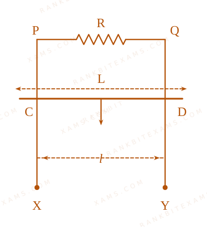
XPQY is a vertical smooth long loop having a total resistance R where PX is parallel to QY and separation between them is l. A constant magnetic field B perpendicular to the plane of the loop exists in the entire space. A rod CD of length L (L > l) and mass m is made to slide down from rest under the gravity as shown in figure. The terminal speed acquired by the rod is \_\_\_\_ m/s.
(g = acceleration due to gravity)
Vertical smooth long loop with sliding rod under gravity and magnetic field.
Sees: Sliding rod in magnetic field reaching terminal speed.
Shortcut: Equate gravitational force with magnetic force iBl$iBl$ at terminal velocity.
Check: Matches option (4). ✓
Chapter Mix
Class 12 Physics: Electromagnetic Induction
Q45jee_main_2026_22_january_morningMutual Induction and Lenz's Law
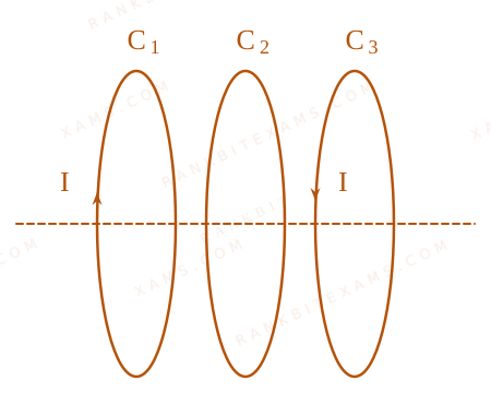
Three identical coils C₁$C_{1}$, C₂$C_{2}$ and C₃$C_{3}$ are closely placed such that they share a common axis. C₂$C_{2}$ is exactly midway. C₁$C_{1}$ carries current I in anti-clockwise direction while C₃$C_{3}$ carries current I in clockwise direction. An induced current flows through C₂$C_{2}$ will be in clockwise direction when
Three coaxial identical coils with opposite current directions.
A.C₁$C_{1}$ and C₃$C_{3}$ move with equal speeds away from C₂$C_{2}$
B.C₁$C_{1}$ moves towards C₂$C_{2}$ and C₃$C_{3}$ moves away from C₂$C_{2}$
C.C₁$\mathrm{C}_1$ moves away from C₂$\mathrm{C}_2$ and C₃$\mathrm{C}_3$ moves towards C₂$\mathrm{C}_2$
D.C₁$C_{1}$ and C₃$C_{3}$ move with equal speeds towards C₂$C_{2}$
Three coaxial identical coils with opposite current directions.
Applying Lenz's law and magnetic field superposition: for induced current in C₂$C_2$ to be clockwise, the net magnetic flux through C₂$C_2$ must change accordingly. When C₁$C_1$ moves towards C₂$C_2$ and C₃$C_3$ moves away from C₂$C_2$, the net field change induces the specified clockwise current.
Pattern Recognition
Sees: Coaxial current-carrying coils in relative motion.
Shortcut: Analyze net magnetic field variation at middle coil C₂$C_2$ using Lenz's law.
Check: Matches option (2). ✓
Chapter Mix
Class 12 Physics: Electromagnetic Induction
More Electromagnetic Induction Questions — jee_main_2025_28_jan_evening
Practice past-year questions one chapter at a time. Pick an exam → subject → chapter and get every PYQ for that topic — pulled together from all past papers — with the chapter's key formulas alongside.