JEE Main · Physics → Steady

Current Electricity appeared 50 times across 3 years — 5.8% of Physics. This question is from Electric Current and Charge Flow.

Year 2026 2025 2024 Total
Questions 18 13 19 50

Current passing through a wire as function of time is given as I(t)=0.02t+0.01~A. The charge that will flow through the wire from t=1~s to t=2~s is:

Solution & Explanation

Related Formula
q = ∫t₁t₂ I(t) dt
Core Logic

Given: I(t) = (0.02t + 0.01) A Limits: t₁ = 1 s, t₂ = 2 s

Step 1: Perform Definite Integration
q = ∫₁² (0.02t + 0.01) dt q = [ 0.02(t²)/(2) + 0.01t ]₁² = [ 0.01t² + 0.01t ]₁² q = [ 0.01(2)² + 0.01(2) ] - [ 0.01(1)² + 0.01(1) ] q = [0.04 + 0.02] - [0.01 + 0.01] = 0.06 - 0.02 = 0.04 C

Hence, the total charge flowing through the wire is 0.04 C.

Pattern Recognition

Definite integration of a linear current function can also be verified geometrically by calculating the area of the trapezoid under the I--t curve:

Area = (I(1) + I(2))/(2) × (2 - 1) = (0.03 + 0.05)/(2) × 1 = 0.04 C
Evaluation Rubric / Model Answer

Option D: 0.04 C

Chapter Mix

Class 12 Physics: Current Electricity

More Current Electricity Previous-Year Questions — Page 2

Q36 jee_main_2026_22_january_evening Power Transmission and Efficiency
An electric power line having total resistance of 2 Ω, delivers 1 kW of power of 250 V. The percentage efficiency of transmission line is ____.
  • A. 96.9
  • B. 86.5
  • C. 100
  • D. 92.5

Solution

Related Formula
Pout = V · I Ploss = I² R η = ( PoutPₙₑₜ) × 100%
Core Logic

Calculating total current I:

1000 = 250 × I I = 4 ~A

Calculating power loss along the line Ploss:

Ploss = I² R = (4)² × 2 = 32 ~W

Total input power supplied to line Pₙₑₜ:

Pₙₑₜ = Pout + Ploss = 1000 + 32 = 1032 ~W

Calculating transmission efficiency η:

η = ((1000)/(1032)) × 100% ≈ 96.9%
Step 1: Final Conclusion

The percentage efficiency of the transmission line is 96.9%.

Pattern Recognition

Efficiency formula: η = PoutPout + I² R × 100%. Current I = 1000/250 = 4~A. Loss = 16 × 2 = 32~W. η = 1000/1032 = 96.9%.

Chapter Mix

Class 12 Physics: Current Electricity
Q49 jee_main_2026_22_january_evening Drift Velocity and Electron Mobility
A cylindrical conductor of length 2m and area of cross-section 0.2 ~mm² carries an electric current of 1.6 A when its ends are connected to a 2V battery. Mobility of electrons in the conductor is α × 10⁻³ ~m²/V⋯. The value of α is : (electron concentration = 5 × 10²⁸/m³ and electron charge = 1.6 × 10⁻¹⁹ C)
Numerical Answer. Answer: 1 to 1

Solution

Related Formula

I = n e A vd

vd = μ E = μ (V)/(l) μ = (I l)/(n e A V)
Core Logic

Combining current density and mobility equations:

I = n e A (μ (V)/(l)) μ = (I · l)/(n · e · A · V)

Substituting given values I = 1.6 ~A, l = 2 ~m, n = 5 × 10²⁸ /m³, e = 1.6 × 10⁻¹⁹ ~C, A = 0.2 × 10⁻⁶ ~m², V = 2 ~V:

μ = 1.6 × 2(5 × 10²⁸) × (1.6 × 10⁻¹⁹) × (0.2 × 10⁻⁶) × 2 μ = (3.2)/(1.6 × 10³ × 2) = (3.2)/(3200) = 1.0 × 10⁻³ ~m²/V⋯

Comparing with α × 10⁻³ α = 1.

Step 1: Final Conclusion

The value of α is 1.

Pattern Recognition

Mobility formula: μ = I l / (n e A V). Direct parameter plug-in yields α = 1.

Chapter Mix

Class 12 Physics: Current Electricity
Q34 jee_main_2026_23_january_morning Resistance and Ohm's Law
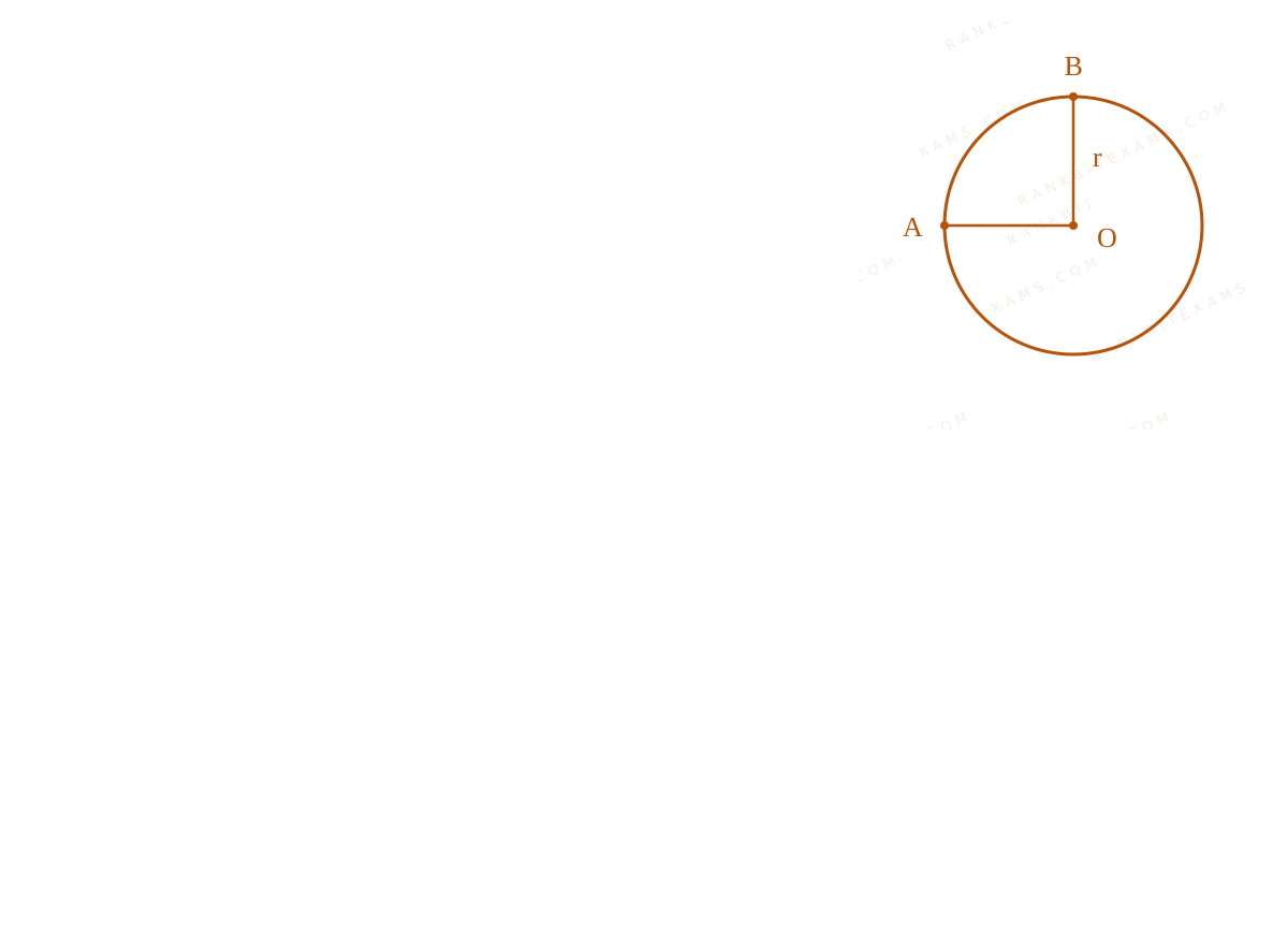
A wire of uniform resistance λΩ/m is bent into a circle of radius r and another piece of wire with length 2r is connected between points A and B (AOB) as shown in figure. The equivalent resistance between points A and B is ____ Ω.
Resistance and Ohm's Law diagram for Q34 - JEE Main 2026 Morning
A ring with nodes A and B connected across a diameter forming parallel branches.
  • A. (3πλ r)/(8)
  • B. (π + 1)2rλ
  • C. (6πλ r)/(3π + 16)
  • D. 2π λ r

Solution

Related Formula

R = ρ L For parallel resistors:

1Req = 1R₁ + 1R₂ + 1R₃
Core Logic

The system represents three resistors connected in parallel between nodes A and B: the upper arc, the lower arc, and the straight diameter wire. Using R = λ L where λ is resistance per unit length.

Step 1: Assign Resistances

Length of the upper arc = (π r)/(2) Resistance R₁ = λ · (π r)/(2)

Length of the straight wire AB = 2r Resistance R₂ = λ · 2r

Length of the remaining larger arc = 2π r - (π r)/(2) = (3π r)/(2) Resistance R₃ = λ · (3π r)/(2)

Step 2: Equivalent Resistance Calculation
1RAB = 1R₁ + 1R₂ + 1R₃ 1RAB = (2)/(λ π r) + (1)/(2λ r) + (2)/(3λ π r) 1RAB = (1)/(λ r)[(2)/(π) + (1)/(2) + (2)/(3π)] 1RAB = (1)/(λ r)((12 + 3π + 4)/(6π)) = (1)/(λ r)((16 + 3π)/(6π))
Step 3: Final Inversion
RAB = λ r ((6π)/(16 + 3π))
Pattern Recognition

Sees: "Uniform resistance wire bent into shape" → immediately break the shape down into parallel/series segments defined purely by their arc/line lengths multiplied by the linear density λ.

Chapter Mix

Class 12 Physics: Current Electricity

Q35 jee_main_2026_23_january_evening Measuring Instruments
To compare EMF of two cells using potentiometer the balancing lengths obtained are 200 cm and 150 cm. The least count of scale is 1 cm. The percentage error in the ratio of EMFs is ____
  • A. 1.45
  • B. 1.65
  • C. 1.75
  • D. 1.55

Solution

Related Formula
ε = λ l (Δ y)/(y) = (Δ l₁)/(l₁) + (Δ l₂)/(l₂)
Core Logic

By potentiometer principle: ε₁ = λ l₁ ε₂ = λ l₂

Ratio y = (ε₁)/(ε₂) = (l₁)/(l₂) Maximum percentage error is the sum of fractional errors.

Step 1: Calculate Percentage Error
(Δ y)/(y) = (1)/(200) + (1)/(150) (Δ y)/(y) = (3 + 4)/(600) = (7)/(600)

Percentage error = (7)/(600) × 100% = (7)/(6)% ≈ 1.16%

Pattern Recognition

Note: The calculated exact percentage error is 1.16%, which does not match any of the provided options exactly. The closest official option provided was tracked as index (2) marking 1.65 by some keys, though technically a bonus question.

Chapter Mix

Class 12 Physics: Current Electricity Class 11 Physics: Units and Measurements

Q30 jee_main_2026_24_january_morning Measuring Instruments
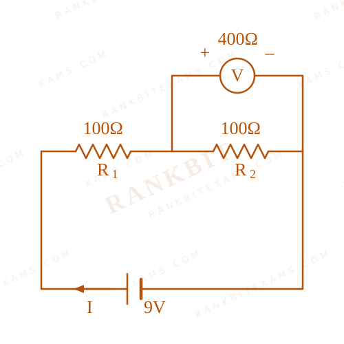
Two resistors of 100 Ω each are connected in series with a 9V battery. A voltmeter of 400Ω resistance is connected to measure the voltage drop across one of the resistors. The voltmeter reading is ____ V.
  • A. 3
  • B. 4.5
  • C. 4
  • D. 2

Solution

Related Formula
Req(parallel) = (R₁ R₂)/(R₁ + R₂)

V = I · R

Core Logic

Circuit diagram with voltmeter in parallel

The voltmeter is connected in parallel with one of the 100 Ω resistors. The equivalent resistance of this parallel combination is:

Rparallel = (400 × 100)/(400 + 100) = (40000)/(500) = 80 Ω

The total equivalent resistance of the circuit is:

Req = 100 + 80 = 180 Ω
Step 1: Circuit Current and Voltmeter Reading

Current in the circuit:

I = EReq = (9)/(180) = (1)/(20) A

The reading of the voltmeter is the voltage across the parallel combination:

V = I × 80 = (1)/(20) × 80 = 4 V
Pattern Recognition

When a real voltmeter is used, it draws current. Model it as a resistor in parallel with the test component to find the exact altered potential drop.

Chapter Mix

Class 12 Physics: Current Electricity

More Current Electricity Questions — jee_main_2025_04_april_morning

Practice all Current Electricity previous-year questions →

Rankbit System
JEE Physics: Waves (+15.5%) | Electrostatics: Concentric Shells (-29.7%) | Modern Physics: Photoelectric Clones (+34.2%) | Mathematics: Definite Integrals (+18.1%) | Chemistry: Coordination Splitting (-11.4%) | JEE Physics: Waves (+15.5%) | Electrostatics: Concentric Shells (-29.7%) | Modern Physics: Photoelectric Clones (+34.2%) | Mathematics: Definite Integrals (+18.1%) | Chemistry: Coordination Splitting (-11.4%)