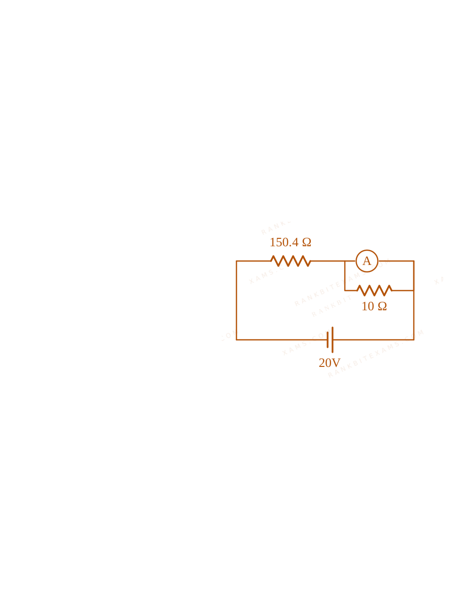
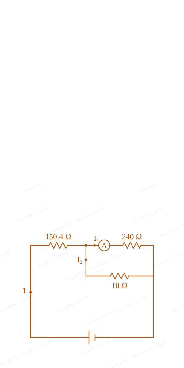
In the figure shown below, a resistance of 150.4Ω$150.4\Omega$ is connected in series to an ammeter A of resistance 240Ω$240\Omega$. A shunt resistance of 10Ω$10\Omega$ is connected in parallel with the ammeter. The reading of the ammeter is ________ mA$\mathrm{mA}$.
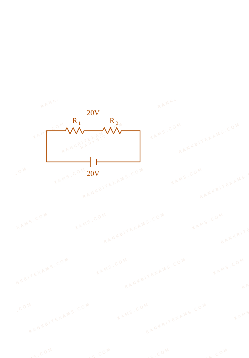
A circuit schematic containing a 20V battery connected in series with a 150.4 ohm resistor and a parallel combination of a 240 ohm ammeter and a 10 ohm shunt resistor.
Numerical Answer Type:
Enter a numerical valueAnswer: 5 to 5+4 marks
Solution & Explanation
Related Formula
Parallel combination of ammeter (RG = 240Ω$R_G = 240\Omega$) and shunt (S = 10Ω$S = 10\Omega$):
Therefore, the reading of the ammeter is 5~mA$5\mathrm{~mA}$.
A circuit schematic containing a 20V battery connected in series with a 150.4 ohm resistor and a parallel combination of a 240 ohm ammeter and a 10 ohm shunt resistor.A circuit schematic containing a 20V battery connected in series with a 150.4 ohm resistor and a parallel combination of a 240 ohm ammeter and a 10 ohm shunt resistor.
Pattern Recognition
Notice how nicely the numbers are set up in JEE Mains questions! The parallel combination of 240Ω$240\Omega$ and 10Ω$10\Omega$ yields exactly 9.6Ω$9.6\Omega$, which beautifully combines with 150.4Ω$150.4\Omega$ to form a perfect integer sum of 160Ω$160\Omega$. This tells you that your intermediate steps are absolutely correct!
Chapter Mix
Class 12 Physics: Current Electricity: Measuring Devices
Keywords:#ammeter shunt current divider#galvanometer conversion ammeter#JEE Main 2025 Morning Q25#Ohm's law equivalent resistance#shunted ammeter#current divider rule#equivalent resistance circuit
More Current Electricity Previous-Year Questions — Page 6
Q2jee_main_2025_04_april_eveningElectric Power
There are 'n' number of identical electric bulbs, each is designed to draw a power p independently from the mains supply. They are now joined in series across the main supply. The total power drawn by the combination is:
Since the bulbs are identical, each has a resistance R = (V²)/(p)$R = \frac{V^2}{p}$.
When n$n$ identical bulbs are connected in series, the total equivalent resistance becomes:
Rₛ = nR$R_s = nR$
Step 1: Calculate Combined Power
The total power drawn across the same mains supply V$V$ is:
Identical appliances connected in series scale down their combined power inversely with count (Pₙₑₜ = P/n$P_{net} = P/n$), identical appliances in parallel scale up combined power linearly (Pₙₑₜ = nP$P_{net} = nP$).
Chapter Mix
Class 12 Physics: Current Electricity
Q6jee_main_2025_04_april_eveningCombination of Resistors
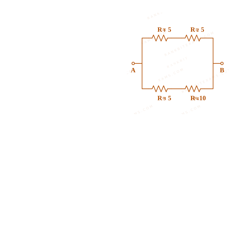
From the combination of resistors with resistance valuesR₁=R₂=R₃=5 Ω$R_{1}=R_{2}=R_{3}=5\ \Omega$ and R₄=10 Ω$R_{4}=10\ \Omega$, which of the following combination is the best circuit to get an equivalent resistance of 6 Ω$6\ \Omega$?
This matches the target value of 6 Ω$6\ \Omega$ perfectly. Circuit diagram analysis for 6 ohm equivalent resistance
Pattern Recognition
Look for symmetric partitions. Standard combinations of values like 10 Ω$10\ \Omega$ and 15 Ω$15\ \Omega$ yield exactly 6 Ω$6\ \Omega$ in parallel.
Chapter Mix
Class 12 Physics: Current Electricity
Qjee_main_2025_04_april_morningElectric Current and Charge Flow
Current passing through a wire as function of time is given as I(t)=0.02t+0.01~A$I(t)=0.02t+0.01\mathrm{~A}$. The charge that will flow through the wire from t=1~s$t=1\mathrm{~s}$ to t=2~s$t=2\mathrm{~s}$ is:
Hence, the total charge flowing through the wire is 0.04 C$0.04\text{ C}$.
Pattern Recognition
Definite integration of a linear current function can also be verified geometrically by calculating the area of the trapezoid under the I--t$I\text{--}t$ curve:
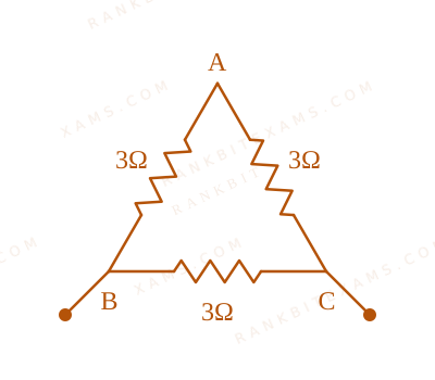
The total resistance of the continuous uniform wire loop is 9Ω$9\Omega$. When bent into an equilateral triangle, it is split into three equal length sections. The resistance of each individual side is:
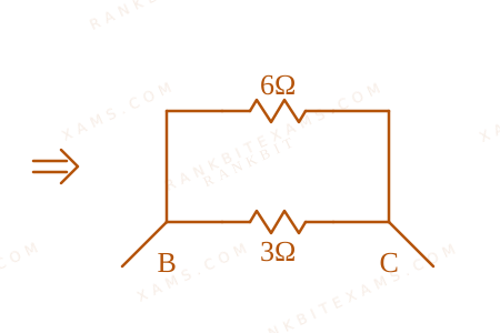
Step 1: Calculating Equivalent Series and Parallel Resistance
As shown in the circuit diagrams Combination of Resistors diagram for Q23 - JEE Main 2025 Morning and Combination of Resistors diagram for Q23 - JEE Main 2025 Morning, measuring across any two vertices means one branch contains a single side resistor (3Ω$3\Omega$), while the other branch contains the remaining two sides connected in series :
For a closed uniform loop with N$N$ equal sides, the parallel resistance measured across adjacent corners always simplifies to (N-1)/(N²) · Rtotal$\frac{N-1}{N^2} \cdot R_{\text{total}}$.
Chapter Mix
Class 12 Physics: Current Electricity
More Current Electricity Questions — jee_main_2025_03_april_morning
Practice past-year questions one chapter at a time. Pick an exam → subject → chapter and get every PYQ for that topic — pulled together from all past papers — with the chapter's key formulas alongside.