JEE Main · Physics ↑ Rising

Electromagnetic Induction appeared 28 times across 3 years — 3.2% of Physics. This question is from Faraday's Law.

Year 2026 2025 2024 Total
Questions 12 6 10 28

The magnetic flux φ (in weber) linked with a closed circuit of resistance 8 Ω varies with time (in seconds) as φ = 5t² - 36t + 1. The induced current in the circuit at t = 2 s is ________ A.

Numerical Answer Type:
Enter a numerical value Answer: 2 to 2 +4 marks

Solution & Explanation

Related Formula
ε = -(dφ)/(dt) I = (|ε|)/(R)
Core Logic

Calculate the time derivative of the magnetic flux to find the induced EMF. Evaluate it at the requested time, and then apply Ohm's law to find the current magnitude.

Step 1: Calculate Induced EMF
ε = -(d)/(dt) (5t² - 36t + 1) ε = -(10t - 36)

At t = 2 s:

ε = - (10 × 2 - 36) ε = -(20 - 36) = 16 V
Step 2: Calculate Induced Current
I = (ε)/(R) = (16)/(8) = 2 A
Pattern Recognition

Flux polynomials (At² - Bt + C) instantly trigger a simple derivative test. Remember to drop the negative sign for final current magnitude unless direction is specifically asked.

Chapter Mix

Class 12 Physics: Electromagnetic Induction

Reference Study Guides

More Electromagnetic Induction Previous-Year Questions — Page 3

Q41 jee_main_2026_23_january_evening Faraday's Law of Induction
A circular loop of radius 7 cm is placed in uniform magnetic field of 0.2 T directed perpendicular to plane of loop. The loop is converted into a square loop in 0.5 s. The EMF induced in the loop is ____ mV.
  • A. 6.6
  • B. 13.2
  • C. 8.25
  • D. 1.32

Solution

Related Formula
EMF = (Δ φ)/(Δ t) = B (A₁ - A₂)/(Δ t)
Core Logic

The magnetic field is constant, but the area changes as the circle deforms into a square. Length of the wire is conserved. Circumference of circular loop = 2π r ≈ 14π cm.

Side length of the new square loop:

4a = 14π a = (7π)/(2) cm
Step 1: Calculate Change in Area
Δ A = Acircle - Asquare A₁ = π r² = π (7)² = 49π cm² A₂ = a² = ( (7π)/(2) )² = (49π²)/(4) cm² Δ A = ( 49π - (49π²)/(4) ) × 10⁻⁴ m²
Step 2: Calculate Flux Change and EMF
Δ φ = B Δ A = 0.2 ( 49π - (49π²)/(4) ) × 10⁻⁴

Using π ≈ 3.1415: 49π ≈ 153.938 (49π²)/(4) ≈ 120.89 Δ A ≈ 33.04 × 10⁻⁴ m²

Wait, taking standard approximations:

Δ φ = 0.2 × 33.07 × 10⁻⁴ = 6.614 × 10⁻⁴ Wb EMF = (Δ φ)/(Δ t) = 6.614 × 10⁻⁴0.5 = 13.228 × 10⁻⁴ V EMF = 1.32 mV
Pattern Recognition

When a loop is deformed into a different shape, perimeter is conserved. For a given perimeter, a circle always encloses maximum area. Subtracting the new area from the old area immediately gives the Δ A driving the induced EMF.

Chapter Mix

Class 12 Physics: Electromagnetic Induction
Q42 jee_main_2026_23_january_evening Mutual Inductance
Suppose a long solenoid of 100 cm length, radius 2 cm having 500 turns per unit length, carries a current I = 10 (ω t) A, where ω = 1000 rad/s . A circular conducting loop (B) of radius 1 cm coaxially slid through the solenoid at a speed v = 1 cm/s . The r.m.s. current through the loop when the coil B is inserted 10 cm inside the solenoid is α/√(2) . The value of α is ____. [Resistance of the loop = 10Ω ]
  • A. 197
  • B. 80
  • C. 280
  • D. 100

Solution

Related Formula
ε = - A (dB)/(dt)

B = μ₀ n I

irms = εrmsR
Core Logic

Since the loop B is well inside the long solenoid (10 cm deep into a 100 cm length), the magnetic field is uniform across its cross-section and approximately equal to the ideal solenoid field B = μ₀ n I. Here n = 500 turns/m. The sliding velocity v just means it's moving through a uniform field region, so motional EMF does not contribute to the flux change; only the transformer EMF (time-varying B field) creates the induced current.

Step 1: Calculate Induced EMF
I = I₀ ω t (dI)/(dt) = I₀ ω ω t ε = A (dB)/(dt) = A μ₀ n (dI)/(dt) = (π r²) μ₀ n (I₀ ω ω t)
Step 2: Calculate RMS Current

Peak EMF ε₀ = π r² μ₀ n I₀ ω.

i₀ = (ε₀)/(R) = (π r² μ₀ n I₀ ω)/(R) irms = i₀√(2) = π r² μ₀ n I₀ ω√(2) R
Step 3: Numerical Substitution
irms = π × (10⁻²)² × (4π × 10⁻⁷) × 500 × 10 × 1000√(2) × 10 irms = π × 10⁻⁴ × 4π × 10⁻⁷ × 5 × 10⁶√(2) × 10 irms = 20π² × 10⁻⁶ × 10√(2) × 10 = 20π²√(2) × 10⁻⁶ A

Using π² ≈ 9.87, 20π² ≈ 197.39. Thus, irms ≈ 197√(2). α = 197.

Pattern Recognition

Motion parallel to uniform field lines inside an ideal solenoid induces no motional EMF. Only the time derivative of the AC current (dI)/(dt) contributes to Faraday induction.

Chapter Mix

Class 12 Physics: Electromagnetic Induction Class 12 Physics: Alternating Current
Q8 jee_main_2025_02_april_evening Self Induction and Energy Stored
A solenoid having area A and length l is filled with a material having relative permeability 2. The magnetic energy stored in the solenoid is :
  • A. (B² A l)/(μ₀)
  • B. (B² A l)/(2 μ₀)
  • C. B² A l
  • D. (B² A l)/(4 μ₀)

Solution

Related Formula
  • Magnetic Energy Density (energy per unit volume):
um = (B²)/(2 μ) = (B²)/(2 μᵣ μ₀)
  • Total Energy stored:
U = um × V = um × (A l)
Core Logic

We are given:

  • Relative permeability μᵣ = 2
  • Permeability of the filled core medium μ = μᵣ μ₀ = 2 μ₀
  • Substitute μᵣ = 2 into the energy density expression:

um = (B²)/(2 (2 μ₀)) = (B²)/(4 μ₀)

Multiply by the total volume of the solenoid (V = A l):

U = um · V = (B²)/(4 μ₀) A l
Pattern Recognition

Sees: Magnetic energy stored in a solenoid with medium relative permeability. Trap: Placing the relative permeability μᵣ in the numerator of the formula instead of the denominator. Shortcut: Magnetic energy density is always inversely proportional to permeability. With medium μ = 2μ₀, energy density is halved compared to free space, giving (B²)/(4μ₀). Multiply by volume Al to get (B² Al)/(4μ₀).

Chapter Mix

Class 12 Physics: Electromagnetic Induction Class 12 Physics: Magnetism and Matter

Q jee_main_2025_04_april_morning Motional Electromotive Force
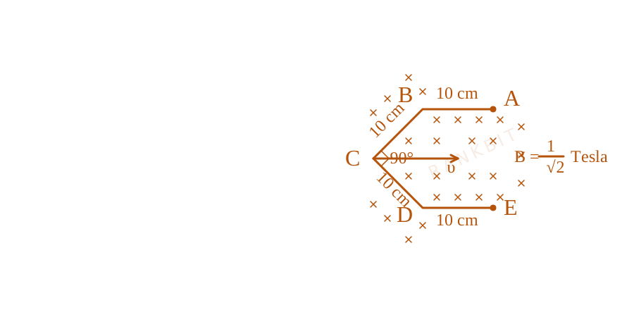
Conductor wire ABCDE with each arm 10~cm in length is placed in magnetic field of 1√(2)~Tesla, perpendicular to its plane. When conductor is pulled towards right with constant velocity of 10~cm/s, induced emf between points A and E is ________ mV.
Conductor wire path geometry layout for Q25 - JEE Main 2025 Morning
The figure outlines a segmented conductive wire trail pulled laterally through an orthogonal inward magnetic field matrix region.
Numerical Answer. Answer: 10 to 10

Solution

Related Formula

Motional electromotive force formula:

ε = B v leff

where leff is the perpendicular component of the straight-line displacement vector connecting the endpoints A and E (lAE) relative to velocity v.

Core Logic

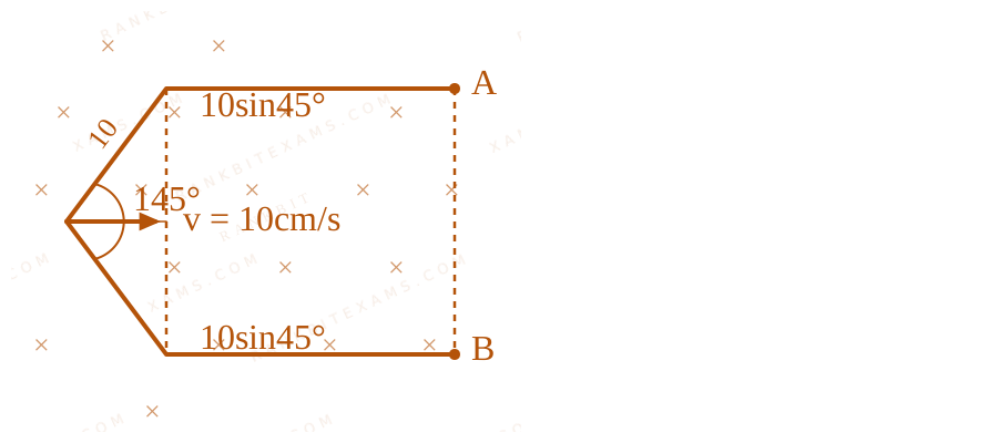
In a uniform magnetic field, the motional EMF induced in any arbitrary conductor wire depends solely on the straight-line displacement vector connecting its endpoints, rather than the detailed path:

ε = ( v × B) · leff

Effective vector length translation resolution mapping for Q25 - JEE Main 2025 Morning
The figure outlines a segmented conductive wire trail pulled laterally through an orthogonal inward magnetic field matrix region.

Step 1: Compute Effective Length

From the geometry of the symmetric wire segments oriented at 45° to the horizontal:

leff = 2 × (10 45°) = 2 × 10 × 1√(2) = 10√(2) cm = 0.1√(2) m
Step 2: Calculate Induced EMF

Substitute the given parameters into the motional EMF expression:

ε = B v leff ε = ( 1√(2)) × (0.1 m/s) × (0.1√(2) m) ε = 1√(2) × 0.1 × 0.1√(2) = 0.01 V = 10 mV
Pattern Recognition

In a uniform magnetic field, motional EMF is path-independent. Replace any zig-zag or curved conductor with an equivalent straight line joining the two endpoints perpendicular to the velocity vector.

Evaluation Rubric / Model Answer

10

Chapter Mix

Class 12 Physics: Electromagnetic Induction

Q1 jee_main_2025_28_jan_evening Motional EMF
A uniform magnetic field of 0.4 T acts perpendicular to a circular copper disc 20 ~cm in radius. The disc is having a uniform angular velocity of 10 π rad s⁻¹ about an axis through its centre and perpendicular to the disc. What is the potential difference developed between the axis of the disc and the rim? ( π = 3.14 )
  • A. 0.0628 V
  • B. 0.5024 V
  • C. 0.2512 V
  • D. 0.1256 V

Solution

Related Formula

The induced electromotive force (EMF) developed between the center and the rim of a rotating disc in a perpendicular magnetic field is given by:

E = (1)/(2) B ω R²
Core Logic

Given parameters from the problem statement [cite: 655, 657, 658]:

  • Magnetic field, B = 0.4 T
  • Radius of the disc, R = 20 cm = 0.2 m
  • Angular velocity, \omega = 10\pi \text{ rad s}^{-1}
  • Substituting the values into the governing formula:

E = (1)/(2) × 0.4 × (10 × 3.14) × (0.2)² E = 0.2 × 31.4 × 0.04 E = 0.2512 V
Step 1: Evaluation

The potential difference developed between the axis of the disc and the rim is precisely 0.2512 V.

Pattern Recognition

For any rotating conductor of length R or a continuous disc rotating about its center in a perpendicular magnetic field, the induced EMF is mathematically equivalent to a single radial rod sweeping the area, leading directly to the formula (1)/(2)Bω R².

Chapter Mix

Class 12 Physics: Electromagnetic Induction

More Electromagnetic Induction Questions — jee_main_2024_31_jan_evening

Practice all Electromagnetic Induction previous-year questions →

Rankbit System
JEE Physics: Waves (+15.5%) | Electrostatics: Concentric Shells (-29.7%) | Modern Physics: Photoelectric Clones (+34.2%) | Mathematics: Definite Integrals (+18.1%) | Chemistry: Coordination Splitting (-11.4%) | JEE Physics: Waves (+15.5%) | Electrostatics: Concentric Shells (-29.7%) | Modern Physics: Photoelectric Clones (+34.2%) | Mathematics: Definite Integrals (+18.1%) | Chemistry: Coordination Splitting (-11.4%)