Two statements are given below:
A. When the forward bias voltage across a p-n junction diode increases above a certain threshold voltage, the diode current increases significantly.
B. This current is called reverse saturation current.
Choose the correct answer from the options given below:
A.Both Statements A and B are false
B.Statement A is true, but Statement B is false
C.Both Statements A and B are true
D.Statement A is false, but Statement B is true
Solution & Explanation
Related Formula
I = Iₛ (eeV/kB T - 1)$$I = I_s \left(e^{eV/k_B T} - 1\right)$$
Core Logic
Statement A is true: across the knee/threshold voltage, forward current increases exponentially.
V-I characteristics solution graph for Q44
Statement B is false: reverse saturation current occurs in reverse bias condition, not forward bias.
Pattern Recognition
Forward bias current vs reverse saturation current definitions.
More Semiconductor Electronics Previous-Year Questions
Qneet_2024_05_may_morningDiode Circuits
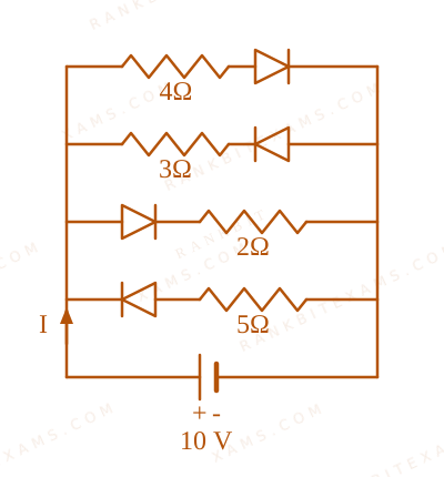
The current I in the circuit shown below is : (All diodes are ideal and identical)
Circuit containing four parallel branches with diodes and resistors connected across a 10V DC power supply.
A.(5)/(3)A$\frac{5}{3}\mathrm{A}$
B.(15)/(2)A$\frac{15}{2}\mathrm{A}$
C.(1)/(3)A$\frac{1}{3}\mathrm{A}$
D.(5)/(9)A$\frac{5}{9}\mathrm{A}$
Solution
Related Formula
I = VReq$$I = \frac{V}{R_{\text{eq}}}$$
Core Logic
For ideal diodes: forward biased resistance = 0, reverse biased resistance = ∞$\infty$.
Branches 1 and 3 are forward biased (diodes conduct).
Branches 2 and 4 are reverse biased (diodes open).
Circuit containing four parallel branches with diodes and resistors connected across a 10V DC power supply.
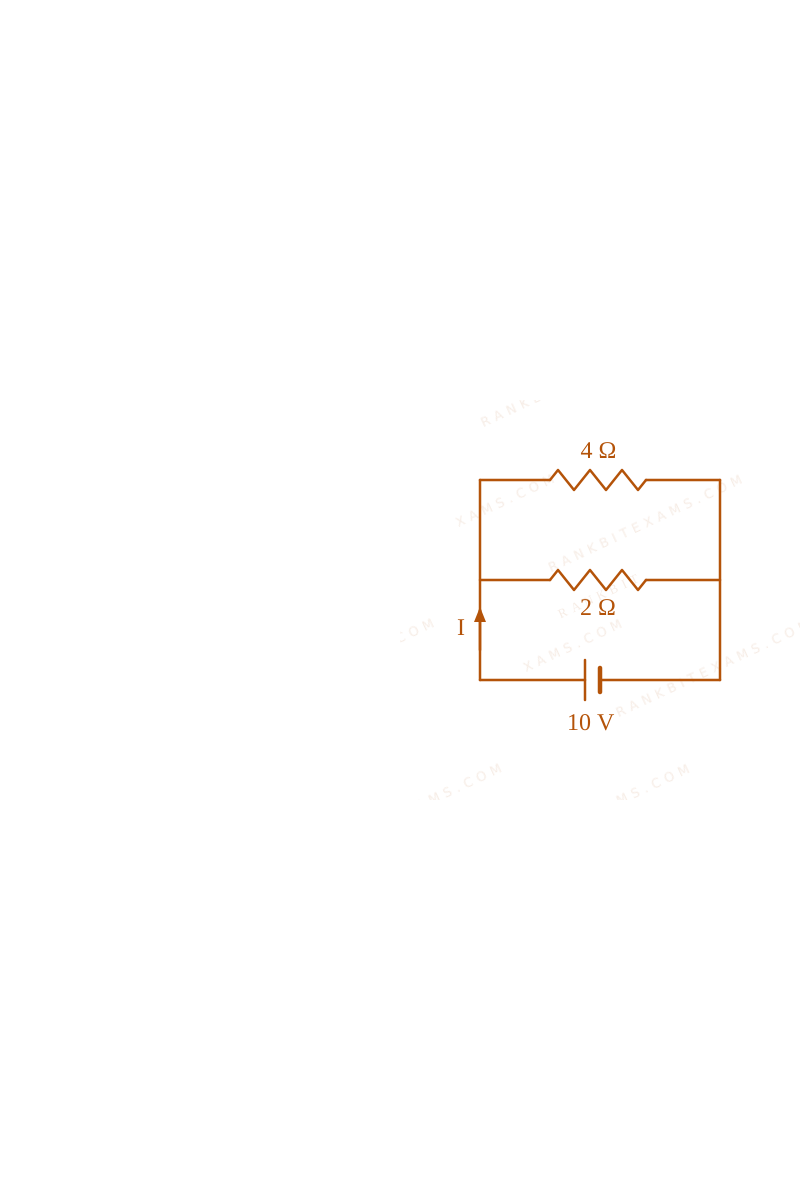
Identify forward vs reverse biased diodes to reduce the circuit to active parallel resistive branches.
Chapter Mix
Class 12 Physics: Semiconductor Electronics
Q24neet_2024_05_may_morningDiode Waveforms
In the circuit shown below, the voltage appearing across the diode D will be of the form:
Diode D in series with resistor R connected to AC voltage source.
A. Option (1)
B. Option (2)
C. Option (3)
D. Option (4)
Solution
Related Formula
vD = vᵢ - vR$v_D = v_i - v_R$
Core Logic
During the positive half cycle, diode is reverse biased, acting as an open circuit. Full voltage drops across diode D$D$.
During the negative half cycle, diode is forward biased, acting as a short circuit (ideal). Voltage drop across diode is zero.
Diode D in series with resistor R connected to AC voltage source.Diode D in series with resistor R connected to AC voltage source.Diode D in series with resistor R connected to AC voltage source.
This matches waveform in option (2).
Pattern Recognition
Reverse biased diode blocks current and drops full input voltage across itself.
Chapter Mix
Class 12 Physics: Semiconductor Electronics
More Semiconductor Electronics Questions — neet_2024_05_may_morning
Practice past-year questions one chapter at a time. Pick an exam → subject → chapter and get every PYQ for that topic — pulled together from all past papers — with the chapter's key formulas alongside.