JEE Main · Physics ↑ Rising

Electromagnetic Induction appeared 28 times across 3 years — 3.2% of Physics. This question is from Motional EMF.

Year 2026 2025 2024 Total
Questions 12 6 10 28

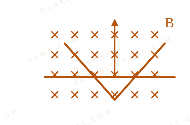
A conducting \bar moves on two conducting rails as shown in the figure. A constant magnetic field B \exists into the page. The \bar starts to move from the vertex at time t = 0 with a constant velocity. If the induced EMF is E ∝ tⁿ , then value of n is
Motional EMF diagram for Q21 - JEE Main 2025 Evening
A linear conductor \bar moving laterally across V-shaped intersecting conducting guide rails.

Numerical Answer Type:
Enter a numerical value Answer: 1 +4 marks

Solution & Explanation

Related Formula

The motional EMF induced across a moving conductor of instantaneous length inside a perpendicular uniform magnetic field is given by:

E = B · · v
Core Logic

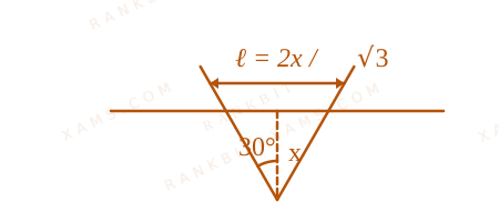
Let the V-shaped guide rails form an \angle, so that the instantaneous length of the conducting \bar grows linearly with its horizontal position distance x from the vertex [cite: 782, 791]:

∝ x

Since the \bar moves with a constant velocity v, its displacement position at any time t is :

x = v · t ∝ v · t

Substituting this time-dependent length into the induced EMF expression :

E = B · · v E ∝ B · (v · t) · v E ∝ t¹

Comparing this to the given relation E ∝ tⁿ gives the exponent[cite: 188, 791]:

n = 1

Step 1: Geometric Analysis

The expanding circuit loop configuration across time is shown below:

Motional EMF geometric analysis diagram for Q21
A linear conductor \bar moving laterally across V-shaped intersecting conducting guide rails.

Pattern Recognition

For \parallel rails, the length remains constant, meaning induced EMF is independent of time (E ∝ t⁰). For V-shaped divergent rails, the effective length increases linearly with distance, making the induced EMF directly proportional to time (E ∝ t¹).

Chapter Mix

Class 12 Physics: Electromagnetic Induction

Reference Study Guides

More Electromagnetic Induction Previous-Year Questions — Page 5

Q42 jee_main_2024_27_jan_morning Faraday's Law
A rectangular loop of length 2.5 m and width 2 m is placed at 60° to a magnetic field of 4 T. The loop is removed from the field in 10 sec. The average emf induced in the loop during this time is:
  • A. -2 V
  • B. +2 V
  • C. +1 V
  • D. -1 V

Solution

Related Formula
emf = -(Δφ)/(Δ t)
Core Logic

Initial magnetic flux is given by φᵢ = B A θ, where A = 2.5 × 2 = 5 m², B = 4 T, and θ = 60° (angle aligned with the axis mapping context rules in the problem source text).

φᵢ = 4 × 5 × (60°) = 20 × 0.5 = 10 Wb

Final flux after removal φf = 0.

Step 1: Compute Induced EMF
emf = -(φf - φᵢ)/(Δ t) = -(0 - 10)/(10) = +1 V
Pattern Recognition

Removal fields yield positive flux variants under canonical sign configurations due to the absolute reduction profile mapped by Lenz/Faraday relationships.

Chapter Mix

Class 12 Physics: Electromagnetic Induction

Q53 jee_main_2024_27_jan_morning Mutual Induction
Two coils have mutual inductance 0.002 H. The current changes in the first coil according to the relation i = i₀ ω t, where i₀ = 5 A and \omega = 50π rad/s. The maximum value of emf in the second coil is (π)/(α) V. The value of α is ______.
Numerical Answer. Answer: 2 to 2

Solution

Related Formula
emf = -M (di)/(dt)
Core Logic

Differentiating the current expression with respect to time:

(di)/(dt) = (d)/(dt)(i₀ ω t) = i₀ ω ω t

Hence, the expression for induced emf is:

emf = -M i₀ ω ω t
Step 1: Isolate Maximum value

The peak magnitude occurs when ω t = 1:

emfmax = M i₀ ω

Substitute given numerical values:

emfmax = 0.002 × 5 × 50π = 0.5π = (π)/(2) V
Step 2: Match with target variable

Comparing (π)/(2) with (π)/(α) gives:

α = 2

Pattern Recognition

Harmonic driving functions induce derivative cosine arrays whose peak amplitudes scale strictly as the product of primary parameters: M · i₀ · ω.

Chapter Mix

Class 12 Physics: Electromagnetic Induction

Q jee_main_2024_29_jan_morning Faraday's and Lenz's Law
A square loop of side 10 ~cm and resistance 0.7 Ω is placed vertically in east-west plane. A uniform magnetic field of 0.20 ~T is set up across the plane in north east direction. The magnetic field is decreased to zero in 1 ~s at a steady rate. Then, magnitude of induced emf is x × 10⁻³ ~V. The value of x is
Numerical Answer. Answer: 2 to 2

Solution

Related Formula

According to Faraday's Law of Electromagnetic Induction, the magnitude of induced EMF (e) is:

e = (Δ φ)/(Δ t)

where magnetic flux φ is defined via dot product:

φ = B · A = B A θ
Core Logic

Let the East-West plane lie vertical along the x-z plane. The normal vector to the loop points along the North direction (along j):

A = (0.1 ~m)² j = 0.01 j ~m²

The uniform magnetic field points North-East, meaning it is at an angle of 45^° to the North vector direction:

B = B 45^° i + B 45^° j = 0.2√(2) i + 0.2√(2) j

Vector reference showing orientation of loop area and North-East magnetic field vectors for Q53

Step 1: Calculate Initial Flux
$φᵢ = B · A = ( 0.2√(2) ) × 0.01 = 2 × 10⁻³√(2) = √(2) × 10⁻³ ~Wb
Step 2: Find Induced EMF

Since the field goes steadily to zero in

Step 2: Find Induced EMF

Since the field goes steadily to zero in $\Delta t = 1 \mathrm{~s}, the final flux value\phi_f = 0:

e = (|0 - φᵢ|)/(1) = √(2) × 10⁻³ ~V
Step 3: Extract x

Comparing this with the target expression

Step 3: Extract x

Comparing this with the target expression $\sqrt{x} \times 10^{-3} \mathrm{~V}:

$x = 2

Pattern Recognition

Be careful when identifying angles between directional plane descriptors. An East-West plane has a normal axis directed North-South. A North-East field makes a clean

Pattern Recognition

Be careful when identifying angles between directional plane descriptors. An East-West plane has a normal axis directed North-South. A North-East field makes a clean $45^\circ$ angle relative to this structural normal line.

Chapter Mix

Class 12 Physics: Electromagnetic Induction

Q51 jee_main_2024_30_january_evening Transformer Efficiency
A power transmission line feeds input power at 2.3 ~kV to a step down transformer with its primary winding having 3000 turns. The output power is delivered at 230 ~V by the transformer. The current in the primary of the transformer is 5 A and its efficiency is 90%. The winding of transformer is made of copper. The output current of transformer is ________ A.
Numerical Answer. Answer: 45 to 45

Solution

Related Formula
η = PoutPᵢₙ Pᵢₙ = Vₚ Iₚ Pout = Vₛ Iₛ
Core Logic

The efficiency η of a transformer is the ratio of output power to input power. We can use this to find the secondary (output) current.

Step 1: Calculate Input Power

Given: Vₚ = 2.3 ~kV = 2300 ~V Iₚ = 5 ~A

Pᵢₙ = 2300 × 5 ~W
Step 2: Calculate Output Power and Current

Efficiency η = 90% = 0.9

Pout = η × Pᵢₙ = 0.9 × 2300 × 5

Since Pout = Vₛ Iₛ and Vₛ = 230 ~V:

Vₛ Iₛ = 230 × Iₛ = 0.9 × 2300 × 5 Iₛ = (0.9 × 2300 × 5)/(230) = 0.9 × 10 × 5 Iₛ = 9 × 5 = 45 ~A
Pattern Recognition

Transformer equations are direct: η Vₚ Iₚ = Vₛ Iₛ. The number of turns (3000) is distractor data not needed unless calculating the secondary turns.

Chapter Mix

Class 12 Physics: Alternating Current

Q60 jee_main_2024_30_jan_morning Motional EMF in Rotating Blades
A ceiling fan having 3 blades of length 80 ~cm each is rotating with an angular velocity of 1200 ~rpm. The magnetic field of earth in that region is 0.5 ~G and angle of dip is 30°. The emf induced across the blades is N π × 10⁻⁵ ~V. The value of N is _______.
Numerical Answer. Answer: 32 to 32

Solution

Related Formula
ε = (1)/(2) Bv ω ² Bv = B δ
Core Logic

For a horizontal fan rotating in the Earth's magnetic field, the blades cut only the vertical component of the magnetic field (Bv). The number of blades is a distractor, as they are all in parallel, meaning the EMF developed across one blade is the same as the EMF across the whole fan setup.

Step 1: Calculate Field and Omega

Vertical component of magnetic field:

Bv = B (30^°) = (0.5 × 10⁻⁴ ~T) × (1)/(2) = 0.25 × 10⁻⁴ ~T = (1)/(4) × 10⁻⁴ ~T

Angular velocity in rad/s:

ω = 2π f = 2π ((1200)/(60)) = 40π ~rad/s
Step 2: Calculate Induced EMF

Length of blade = 80 ~cm = 0.8 ~m.

ε = (1)/(2) Bv ω ² ε = (1)/(2) ((1)/(4) × 10⁻⁴) (40π) (0.8)² ε = (1)/(8) × 10⁻⁴ × 40π × 0.64 ε = 5π × 10⁻⁴ × 0.64 ε = 3.2π × 10⁻⁴ ~V ε = 32π × 10⁻⁵ ~V
Step 3: Extract N

Given ε = Nπ × 10⁻⁵ ~V, we can directly see that N = 32.

Pattern Recognition

Motional EMF for rotating rods acts like a battery. Multiple identical blades radiating from the center to the rim behave like multiple identical batteries in parallel; the total voltage does not stack. Isolate Bv for horizontal spinners.

Chapter Mix

Class 12 Physics: Electromagnetic Induction Class 12 Physics: Magnetism and Matter

More Electromagnetic Induction Questions — jee_main_2025_28_jan_evening

Practice all Electromagnetic Induction previous-year questions →

Rankbit System
JEE Physics: Waves (+15.5%) | Electrostatics: Concentric Shells (-29.7%) | Modern Physics: Photoelectric Clones (+34.2%) | Mathematics: Definite Integrals (+18.1%) | Chemistry: Coordination Splitting (-11.4%) | JEE Physics: Waves (+15.5%) | Electrostatics: Concentric Shells (-29.7%) | Modern Physics: Photoelectric Clones (+34.2%) | Mathematics: Definite Integrals (+18.1%) | Chemistry: Coordination Splitting (-11.4%)