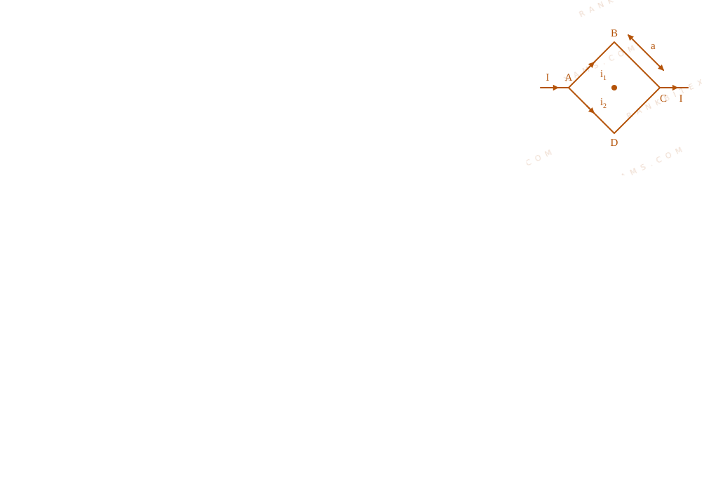
Figure shows a current carrying square loop ABCD of edge length is 'a' lying in a plane. If the resistance of the ABC part is r$r$ and that of ADC part is 2r$2r$, then the magnitude of the resultant magnetic field at centre of the square loop is:
A schematic of a square current loop labeled ABCD with path ABC having resistance r and path ADC having resistance 2r, causing incoming current to divide.
where,
Bwire$B_{\text{wire}}$ = magnetic field due to a straight wire segment
d$d$ = perpendicular distance from center to wire segment (d = a/2$d = a/2$)
θ₁, θ₂$\theta_1, \theta_2$ = subtended angles at the center
Core Logic
The loop parts ABC and ADC are in parallel. Let total current entering corner A and leaving corner C be I$I$.
Resistance of path ABC = r$r$
Resistance of path ADC = 2r$2r$
Using current divider rule:
Current in path ABC, I₁ = (2r)/(r + 2r) I = (2)/(3) I$I_1 = \frac{2r}{r + 2r} I = \frac{2}{3} I$
Current in path ADC, I₂ = (r)/(r + 2r) I = (1)/(3) I$I_2 = \frac{r}{r + 2r} I = \frac{1}{3} I$
Now, calculate the magnetic field contribution at center O$O$:
Distance of center from each of the 4 wire segments is d = (a)/(2)$d = \frac{a}{2}$.
For each segment, the angles are θ₁ = θ₂ = 45^°$\theta_1 = \theta_2 = 45^\circ$:
Sees: Current divides into parallel paths of a symmetric loop.
Trap: In a completely symmetric square loop (equal resistances), the net magnetic field at the center is exactly 0$0$. However, here the paths have unequal resistances (r$r$ and 2r$2r$), which prevents total cancellation.
Shortcut: Find the net effective current imbalance Δ I = I₁ - I₂ = (2)/(3)I - (1)/(3)I = (1)/(3)I$\Delta I = I_1 - I_2 = \frac{2}{3}I - \frac{1}{3}I = \frac{1}{3}I$. The magnitude is simply the magnetic field contribution of two sides carrying this net imbalance. ✓
Chapter Mix
Class 12 Physics: Magnetic Effects of Current
A schematic of a square current loop labeled ABCD with path ABC having resistance r and path ADC having resistance 2r, causing incoming current to divide.
Keywords:#Square loop magnetic field at center#JEE Main 2025 Evening Q14#Biot-Savart Law square loop#Resistive current division magnetic field#current carrying loop#square loop#magnetic field at center#resistance division
More Magnetic Effects of Current Previous-Year Questions — Page 6
Qjee_main_2025_28_jan_eveningBiot Savart Law
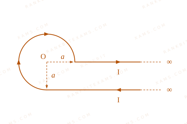
An infinite wire has a circular bend of radius a$a$ , and carrying a current I as shown in figure. The magnitude of magnetic field at the origin O of the arc is given by:
An infinite current carrying wire presenting a three-quarter circular bend around center origin O.
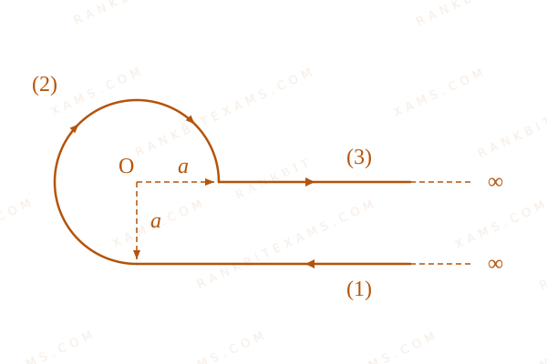
Let us decompose the structure into three functional parts as mapped out below:
An infinite current carrying wire presenting a three-quarter circular bend around center origin O.
Segment 1 (Incoming semi-infinite line): The straight line extends to infinity, with its terminating tip at a perpendicular distance a$a$ from origin O$O$. Using the right-hand grip rule, the direction points into the page:
Segment 2 (Three-quarter circular loop): The loop forms an angle of θ = (3π)/(2)$\theta = \frac{3\pi}{2}$ radians around O$O$. The field points into the page:
Always check the axis alignment first. Any straight wire segment whose extended line passes directly through the field point contributes exactly zero to the total magnetic field value.
Qjee_main_2025_29_jan_morningAmpere\'s Circuital Law
Consider a long straight wire of a circular cross-section (radius a) carrying a steady current I. The current is uniformly distributed across this cross-section. The distances from the centre of the wire\'s cross-section at which the magnetic field [inside the wire, outside the wire] is half of the maximum possible magnetic field, any where due to the wire, will be
A galvanometer has a resistance of 50~Ω$50\mathrm{~\Omega}$ and it allows maximum current of 5~mA$5\mathrm{~mA}$. It can be converted into voltmeter to measure upto 100~V$100\mathrm{~V}$ by connecting in series a resistor of resistance:
Voltmeter resistance is always high because it is connected in parallel to circuits to prevent current drawing leaks.
Chapter Mix
Class 12 Physics: Moving Charges and Magnetism
Class 12 Physics: Current Electricity
Qjee_main_2024_01_february_morningMagnetic Field due to a Current Element
A regular polygon of 6 sides is formed by bending a wire of length 4pi$4pi$ meter. If an electric current of 4pisqrt3~A$4pisqrt{3}\mathrm{~A}$ is flowing through the sides of the polygon, the magnetic field at the centre of the polygon would be x × 10⁻⁷~T$x \times 10^{-7}\mathrm{~T}$. The value of x$x$ is:
Numerical Answer.Answer: 72 to 72
Solution
Related Formula
Magnetic field due to a straight wire segment of length 2L$2L$ at distance r$r$:
Total perimeter = 6 · a = 4π side length a = (4π)/(6) = (2π)/(3)~m$= 6 \cdot a = 4\pi \implies \text{side length } a = \frac{4\pi}{6} = \frac{2\pi}{3}\mathrm{~m}$.
For a regular hexagon segment, the interior angles relative to the normal vector are θ₁ = θ₂ = 30^°$\theta_1 = \theta_2 = 30^\circ$.
The normal distance r$r$ from the center to a side is:
For regular polygons, the normal distance r$r$ to the side is always r = (a)/(2) ((π)/(n))$r = \frac{a}{2}\cot(\frac{\pi}{n})$. The contribution from all n$n$ symmetric segments adds up constructively.
Chapter Mix
Class 12 Physics: Moving Charges and Magnetism
Q39jee_main_2024_29_january_eveningMotion of Charged Particle in Magnetic Field
Two particles X and Y having equal charges are being accelerated through the same potential difference. Thereafter they enter normally in a region of uniform magnetic field and describes circular paths of radii R₁$R_1$ and R₂$R_2$ respectively. The mass ratio of X and Y is:
A.((R₂)/(R₁))²$\left(\frac{R_2}{R_1}\right)^2$
B.((R₁)/(R₂))²$\left(\frac{R_1}{R_2}\right)^2$
C.((R₁)/(R₂))$\left(\frac{R_1}{R_2}\right)$
D.((R₂)/(R₁))$\left(\frac{R_2}{R_1}\right)$
Solution
Related Formula
The radius R$R$ of the path of a charged particle moving perpendicular to a magnetic field B$B$ is:
R = (mv)/(qB) = (p)/(qB)$$R = \frac{mv}{qB} = \frac{p}{qB}$$
In terms of kinetic energy K$K$:
R = √(2mK)qB$$R = \frac{\sqrt{2mK}}{qB}$$
Since the particle is accelerated through potential V$V$, kinetic energy K = qV$K = qV$:
Shortcut: Whenever charges and potential differences are equal, the radius of orbit in a magnetic field scales as R ∝ √(m)$R \propto \sqrt{m}$. Squaring both sides yields m ∝ R²$m \propto R^2$ instantly.
Chapter Mix
Class 12 Physics: Moving Charges and Magnetism
More Magnetic Effects of Current Questions — jee_main_2025_08_april_evening
Practice past-year questions one chapter at a time. Pick an exam → subject → chapter and get every PYQ for that topic — pulled together from all past papers — with the chapter's key formulas alongside.