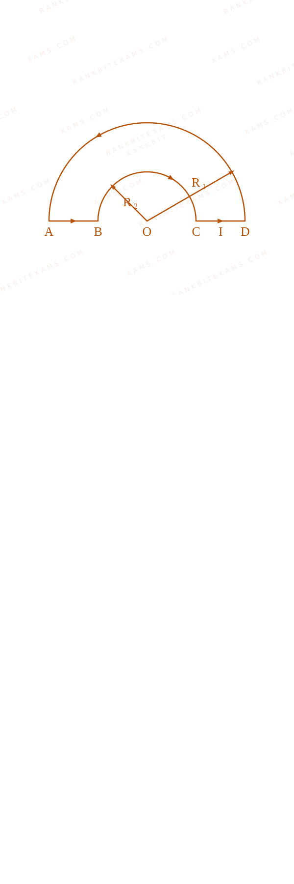
A loop ABCDA, carrying current I = 12~A$I = 12\mathrm{~A}$, is placed in a plane, consists of two semi-circular segments of radius R₁ = 6π~m$R_1 = 6\pi\mathrm{~m}$ and R₂ = 4π~m$R_2 = 4\pi\mathrm{~m}$. The magnitude of the resultant magnetic field at center O is k× 10⁻⁷~T$k\times 10^{-7}\mathrm{~T}$ The value of k is ________. (Given μ₀=4π×10⁻⁷~T· m· A⁻¹$\mu_{0}=4\pi\times10^{-7}\mathrm{~T\cdot m\cdot A}^{-1}$)
A current loop containing two concentric semicircular segments of radii R1 and R2 connected by radial straight segments, with common center O.
Numerical Answer Type:
Enter a numerical valueAnswer: 1 to 1+4 marks
Solution & Explanation
Related Formula
Magnetic field at the center of a circular segment of angle θ$\theta$:
Let's analyze the contributions from each part of the loop to the magnetic field at the center O$O$:
The straight wire segments AB$AB$ and CD$CD$ lie along radial lines passing directly through O$O$. Since d l ∥ r$d\vec{l} \parallel \vec{r}$, their magnetic field contribution is zero:
BAB = BCD = 0$$B_{\text{AB}} = B_{\text{CD}} = 0$$
Semicircular segment of radius R₂ = 4π~m$R_2 = 4\pi\mathrm{~m}$ carries current creating a field pointing out of the page (by right-hand rule):
BR2 = (μ₀ I)/(4 R₂) (Out of page)$$B_{R2} = \frac{\mu_0 I}{4 R_2} \quad (\text{Out of page})$$
Semicircular segment of radius R₁ = 6π~m$R_1 = 6\pi\mathrm{~m}$ carries current creating a field pointing into the page:
Comparing this to k × 10⁻⁷~T$k \times 10^{-7}\mathrm{~T}$:
k = 1$k = 1$
Pattern Recognition
Notice how the radial straight wires never contribute to the magnetic field at the center. Semicircles with opposite currents simply subtract. Symmetrizing the math early by factoring out (μ₀ I)/(4π)$\frac{\mu_0 I}{4\pi}$ makes the calculations incredibly neat and quick.
Chapter Mix
Class 12 Physics: Magnetic Effects of Current: Biot-Savart Law
Keywords:#Biot Savart concentric semicircles#magnetic field circular segment#JEE Main 2025 Morning Q24#resultant magnetic field concentric#magnetic field loop#semicircular segments#Biot Savart law
More Magnetic Effects of Current Previous-Year Questions — Page 7
Q54jee_main_2024_29_january_eveningMagnetic Force on a Charge
A charge of 4.0$4.0\ \mu\text{C}$ is moving with a velocity of 4.0 × 10⁶ ms⁻¹$4.0 \times 10^{6}\text{ ms}^{-1}$ along the positive y-axis under a magnetic field B$\vec{B}$ of strength (2 k) T$(2\hat{k})\text{ T}$. The force acting on the charge is x i N$x\hat{i}\text{ N}$. The value of x$x$ is ________.
Numerical Answer.Answer: 32 to 32
Solution
Related Formula
The magnetic force on a moving charge is given by the Lorentz force equation:
F = q ( v × B)$$\vec{F} = q (\vec{v} \times \vec{B})$$
Since j × k = i$\hat{j} \times \hat{k} = \hat{i}$:
F = 32 i N$$\vec{F} = 32\hat{i}\text{ N}$$
Comparing this to x i N$x\hat{i}\text{ N}$, we find:
x = 32$x = 32$
Pattern Recognition
Cross-product check: j × k = i$\hat{j} \times \hat{k} = \hat{i}$. The product of the scalar terms (4.0 × 10⁻⁶) × (4.0 × 10⁶) × 2$(4.0 \times 10^{-6}) \times (4.0 \times 10^6) \times 2$ immediately simplifies to 4 × 4 × 2 = 32$4 \times 4 \times 2 = 32$.
Chapter Mix
Class 12 Physics: Moving Charges and Magnetism
Qjee_main_2024_27_jan_morningMagnetic Field due to Long Straight Wire
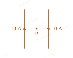
Two long, straight wires carry equal currents in opposite directions as shown in the figure. The separation between the wires is 5.0 cm$5.0\text{ cm}$. The magnitude of the magnetic field at a point P$P$ midway between the wires is ______ $\mu\text{T}$. (Given : μ₀ = 4π × 10⁻⁷ T ⁻¹$\mu_{0} = 4\pi \times 10^{-7}\text{ T}\cdot\text{m}\cdot\text{A}^{-1}$, and each wire carries a current of 10 A$10\text{ A}$).
The diagram maps two vertical wires carrying anti-parallel currents of 10 A separated by 5.0 cm, with central node P denoting the common field contribution site.
Numerical Answer.Answer: 160 to 160
Solution
Related Formula
B = (μ₀ i)/(2π r)$$B = \frac{\mu_0 i}{2\pi r}$$
Core Logic
Using the right-hand grip rule, both anti-parallel wire systems generate field arrays pointing in the exact same direction at the central midway coordinate. Hence, their field contributions add up directly:
Where i = 10 A$i = 10\text{ A}$, total distance = 5 cm r = 2.5 cm = 2.5 × 10⁻² m$= 5\text{ cm} \implies r = 2.5\text{ cm} = 2.5 \times 10^{-2}\text{ m}$.
Anti-parallel current pairs generate collaborative field additions inside their spatial boundary zone, rather than destructive structural cancellations.
Chapter Mix
Class 12 Physics: Moving Charges and Magnetism
Q34jee_main_2024_27_jan_morningLorentz Force
A proton moving with a constant velocity passes through a region of space without any change in its velocity.
If E$\vec{E}$ and B$\vec{B}$ represent the electric and magnetic fields respectively, then the region of space may have:
(A) E = 0, B = 0$E = 0, B = 0$
(B) E = 0, B ≠ 0$E = 0, B \neq 0$
(C) E ≠ 0, B = 0$E \neq 0, B = 0$
(D) E ≠ 0, B ≠ 0$E \neq 0, B \neq 0$
Choose the most appropriate answer from the options given below:
A.(A), (B) and (C) only$\text{(A), (B) and (C) only}$
B.(A), (C) and (D) only$\text{(A), (C) and (D) only}$
C.(A), (B) and (D) only$\text{(A), (B) and (D) only}$
D.(B), (C) and (D) only$\text{(B), (C) and (D) only}$
Solution
Related Formula
Fₙₑₜ = q E + q( v × B)$$\vec{F}_{\text{net}} = q\vec{E} + q(\vec{v} \times \vec{B})$$
Core Logic
For velocity to remain constant, the net force must be zero:
q E + q( v × B) = 0$$q\vec{E} + q(\vec{v} \times \vec{B}) = 0$$
Let's evaluate the cases:
Case (A): If E=0$E=0$ and B=0$B=0$, F = 0$\vec{F} = 0$. (Possible)
Case (B): If E=0$E=0$ and B ≠ 0$B \neq 0$, the magnetic force is zero if v$\vec{v}$ is parallel or antiparallel to B$\vec{B}$ (i.e., v × B = 0$\vec{v} \times \vec{B} = 0$). (Possible)
Case (C): If E ≠ 0$E \neq 0$ and B=0$B=0$, F = q E ≠ 0$\vec{F} = q\vec{E} \neq 0$, velocity must change. (Not possible)
Case (D): If E ≠ 0$E \neq 0$ and B ≠ 0$B \neq 0$, the electric and magnetic forces can balance each other perfectly if q E = -q( v × B)$q\vec{E} = -q(\vec{v} \times \vec{B})$. (Possible)
Step 1: Conclusion
Hence, statements (A), (B), and (D) represent valid situations where velocity can remain constant.
Pattern Recognition
Velocity filter / velocity selector setups utilize crossed fields where electric fields perfectly balance magnetic components, an archetype of Case (D).
Chapter Mix
Class 12 Physics: Moving Charges and Magnetism
Qjee_main_2024_29_jan_morningGalvanometer and its Conversions
A galvanometer having coil resistance 10 Ω$10 \, \Omega$ shows a full scale deflection for a current of 3 ~mA$3 \mathrm{~mA}$. For it to measure a current of 8 ~A$8 \mathrm{~A}$, the value of the shunt should be:
A.3 × 10⁻³ Ω$3 \times 10^{-3} \, \Omega$
B.4.85 × 10⁻³ Ω$4.85 \times 10^{-3} \, \Omega$
C.3.75 × 10⁻³ Ω$3.75 \times 10^{-3} \, \Omega$
D.2.75 × 10⁻³ Ω$2.75 \times 10^{-3} \, \Omega$
Solution
Related Formula
To convert a galvanometer into an ammeter, a small resistance called a shunt (S$S$) is connected in parallel with the galvanometer (G$G$):
Ig G = (I - Ig) S S = (Ig G)/(I - Ig)$$I_g G = (I - I_g) S \implies S = \frac{I_g G}{I - I_g}$$
where,
G$G$ = resistance of the galvanometer coil
Ig$I_g$ = full-scale deflection current of the galvanometer
I$I$ = total current to be measured
S$S$ = shunt resistance
Therefore, the required value of the shunt resistance is 3.75 × 10⁻³ Ω$3.75 \times 10^{-3} \, \Omega$.
Circuit diagram of conversion of a galvanometer into an ammeter using parallel shunt resistance for Q42
Pattern Recognition
Since I gg Ig$I \gg I_g$, the value I - Ig$I - I_g$ in the denominator can be approximated directly as I$I$ for a very accurate quick shortcut in choice selection: S ≈ (Ig G)/(I) = (0.03)/(8) = 3.75 × 10⁻³ Ω$S \approx \frac{I_g G}{I} = \frac{0.03}{8} = 3.75 \times 10^{-3} \, \Omega$.
Chapter Mix
Class 12 Physics: Moving Charges and Magnetism
Qjee_main_2024_29_jan_morningGalvanometer and its Conversions
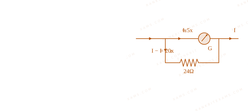
The deflection in moving coil galvanometer falls from 25 divisions to 5 division when a shunt of 24 Ω$24 \, \Omega$ is applied. The resistance of galvanometer coil will be:
A.12 Ω$12 \, \Omega$
B.96 Ω$96 \, \Omega$
C.48 Ω$48 \, \Omega$
D.100 Ω$100 \, \Omega$
Solution
Related Formula
For a shunted galvanometer, the potential difference across the galvanometer is equal to the potential difference across the shunt resistor:
Ig G = (I - Ig) S$$I_g G = (I - I_g) S$$
Core Logic
Let the current sensitivity per division be x$x$.
Initially, without the shunt, the total current I$I$ gives a full scale deflection of 25 divisions:
I = 25x$I = 25x$
Schematic diagrams representing galvanometer before and after shunting for Q44
When the shunt (S = 24 Ω$S = 24 \, \Omega$) is connected in parallel, the current passing through the galvanometer branch (Ig$I_g$) corresponds to a deflection of 5 divisions:
Ig = 5x$I_g = 5x$
Schematic diagrams representing galvanometer before and after shunting for Q44
Therefore, the resistance of the galvanometer coil is 96 Ω$96 \, \Omega$.
Pattern Recognition
The deflection is directly proportional to the branch current. A drop from 25 divisions to 5 divisions means only (5)/(25) = (1)/(5)$\frac{5}{25} = \frac{1}{5}$ of the total current flows through the galvanometer, leaving (4)/(5)$\frac{4}{5}$ to go through the shunt. Hence, the galvanometer resistance must be 4 times the shunt resistance.
Chapter Mix
Class 12 Physics: Moving Charges and Magnetism
More Magnetic Effects of Current Questions — jee_main_2025_03_april_morning
Practice past-year questions one chapter at a time. Pick an exam → subject → chapter and get every PYQ for that topic — pulled together from all past papers — with the chapter's key formulas alongside.
